V Plotter: V-Bot
Technical Objective
Built a V-plotter that draws by hanging a pen carriage from two stepper motors on strings. The motors adjust string lengths to move the pen across a surface based on inverse kinematics calculations.
Development Timeline
I built this over a few days using borrowed time between school and other projects.
- Design: I modeled the frame and carriage during classes.
- Kinematics: I worked out the math for the inverse kinematics by hand.
- Build: I assembled everything and integrated the code in a single 9-hour session after school.
Hardware Integration
The system runs on 12V from a USB-C Power Delivery supply (2A maximum).
- Power Rails: The 12V powers the stepper drivers directly. A 5V buck converter steps it down for the logic board and servo. The ESP32 uses its internal 3.3V regulator.
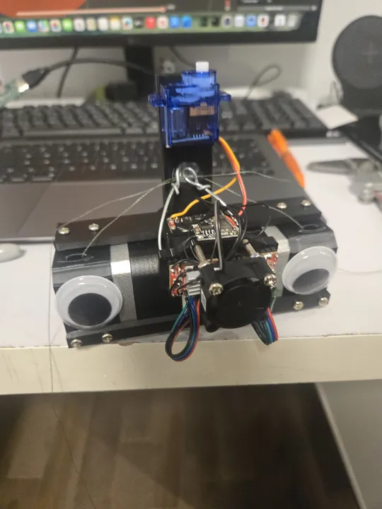
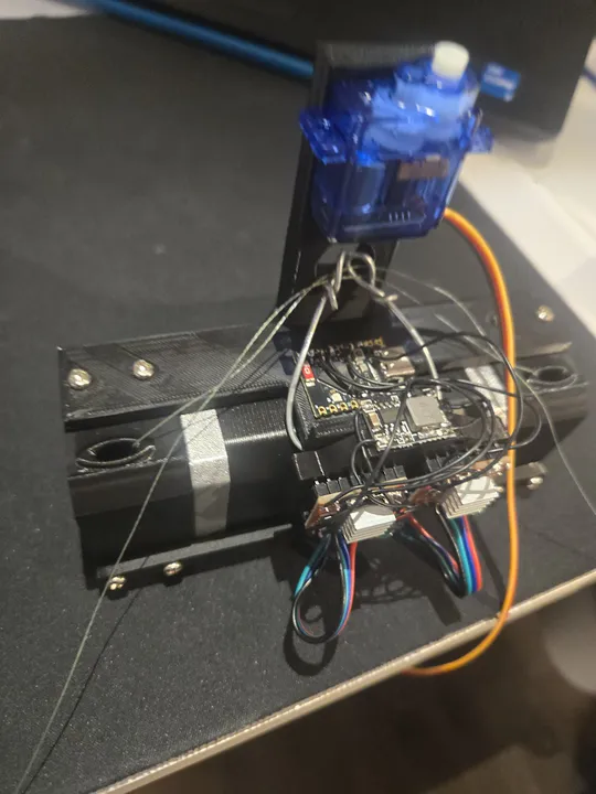
- Main Controller: ESP32-C3 running a web server for wireless drawing commands and status monitoring.
- Motors: Two NEMA 17 steppers suspended from the frame using high-tensile string.
- Pen Control: A small servo motor raises and lowers the pen (Z-axis).
- Cooling: A small fan blows over the stepper drivers to prevent overheating.
Inverse Kinematics
The math for this robot was the hardest part. I had to write a custom engine that calculates exactly how long each string needs to be to reach a specific point on the whiteboard.
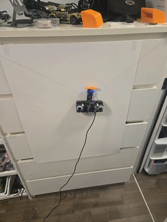
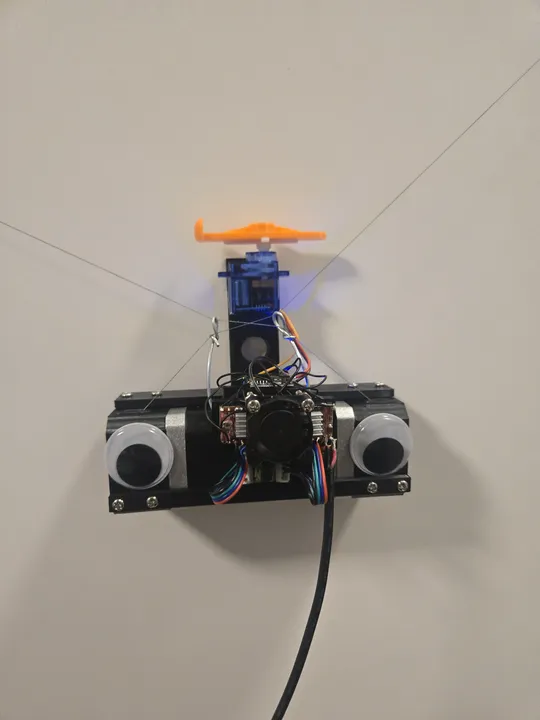 The robot hanging on a whiteboard. It uses two strings to move the pen.
Instead of simple X and Y coordinates, the robot thinks in string lengths. I programmed it to "home" itself by pulling both strings all the way in, giving it a known starting point before it begins to draw.
Bill of Materials
I tried to make this as cheap as possible by using common parts.
- Motion Kit: $20.00
- Brain (ESP32-C3): $1.00
- Power Parts: $2.50
- Servo Motor: $2.00
- 3D Printed Frame: $5.00
Total Cost: ~$30.50
Post-Mortem
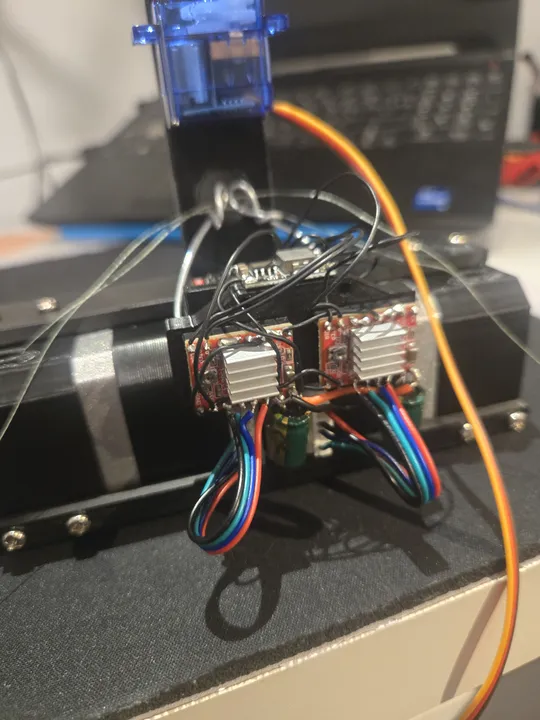
One big failure happened during testing: the cheap motor drivers I bought couldn't handle the power needed to lift the pen. They overheated and literally burned out.
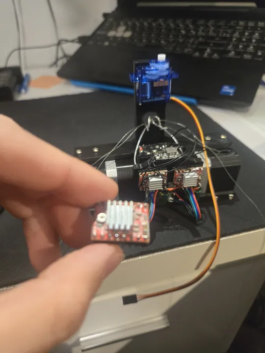 One of the motor drivers that failed during testing. Next time, I'll use higher-quality parts.
Built at 16 years 11 months