Smart Ebike Charger
The ebike runs on a custom 12S pack built from two 6S LiPo packs in series. The only charger available was the 6S LiHV unit that originally shipped with a Leafboard Gen 1 electric skateboard — the same board whose motor was later salvaged for the ebike v1 and the underwater scooter v1. That charger is designed to push cells to 4.35V each (26.1V for a 6S pack) rather than the standard LiPo maximum of 4.2V per cell (25.2V). Running a LiHV charger on standard LiPo cells risks overcharge, puffing, and eventual cell failure.
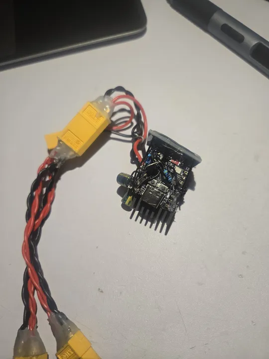
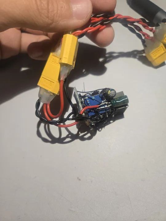
The solution was a relay-based cutoff controller that intercepts the charger output and disconnects it at the right moment.
The Cutoff Design
I built a simple relay-cutoff for a LiHV charger using an ESP32. I added a timer to make sure it doesn't shut off too early when the voltage drops under load. For a version 2, I would build a proper charging circuit, as mechanical relays aren't the best for cutting high power.
Hardware
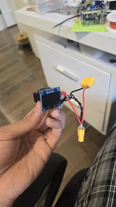
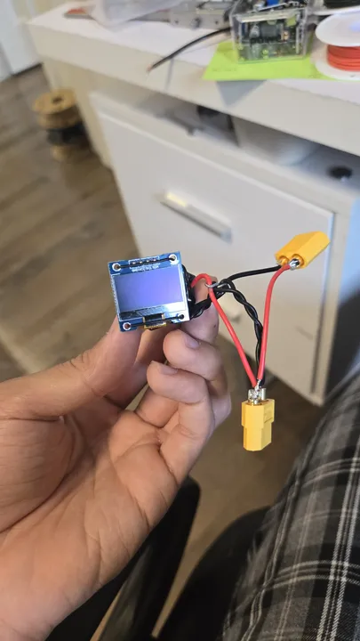
The system uses a small ESP32-C3 computer and a relay to handle the power. I added an OLED screen so I can see the charging progress and the device's IP address at a glance.
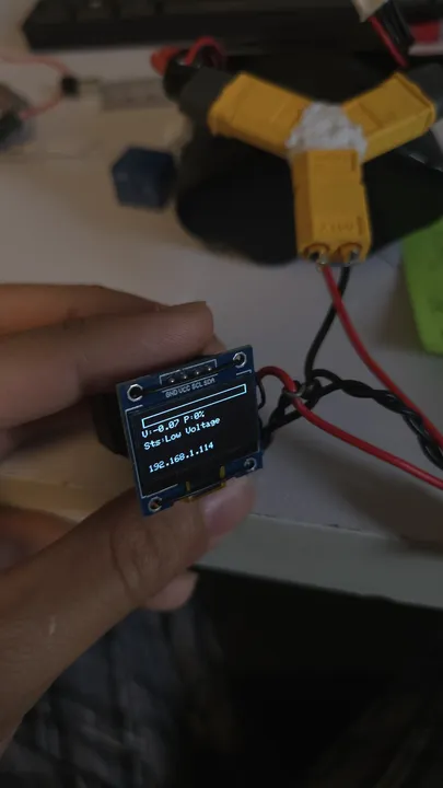 The OLED screen shows the battery voltage and a progress bar.
Web Interface
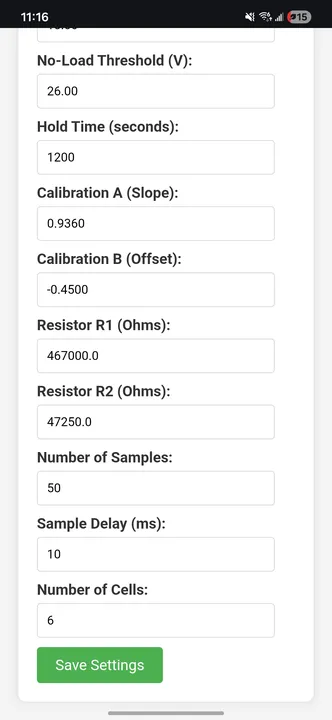
When you plug it in, the charger connects to your WiFi. You can open a dashboard on your phone or laptop to see exactly what's happening. I added buttons to manually turn the charger on or off, and a settings page to change things like the cutoff voltage without needing to rewrite the code.
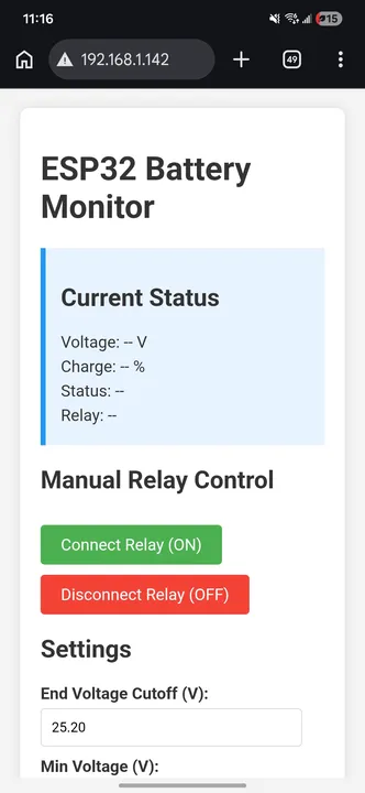 The web interface lets you monitor and control the charger from any device.
Bill of Materials
AliExpress pricing; ESP32-C3 was $1.
| Component | Unit Cost |
|---|---|
| ESP32-C3 Super Mini | $1.00 |
| SSD1306 OLED display | $1.10 |
| L7805CV 5V LDO regulator | $0.45 |
| 5V relay module | $1.00 |
| NPN transistor | $0.05 |
| Resistors (3 total) | $0.02 |
| Electrolytic capacitors (2 total) | $1.00 |
| Wire (22AWG) | $0.50 |
| XT60 connectors | $0.75 |
| Total | ~$5.00 |
Control Logic
The firmware runs four safety checks:
- No-load detection: open circuit detection.
- Under-voltage protection: prevents over-discharged cells from charging.
- Charge complete: prevents relay oscillation.
- Normal charging: cuts off the relay when voltage and time thresholds are met.
Files & Links
Built at 16 years 3 months