Head Tracking DJI O3 Air Unit
A 2-axis head-tracking gimbal system built for the DJI Goggles 3 and O3 Air Unit. Two ESP32-C3s communicate over ESP-NOW — one on the goggles reading head orientation, one on the drone driving the servos.
The mechanical design was sketched out during a math exam. The teacher was not pleased.
Hardware
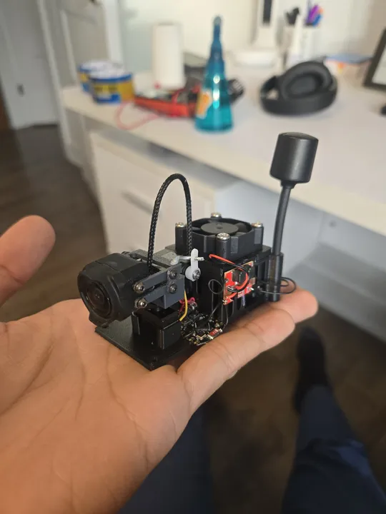
The gimbal is custom-designed and 3D printed. It uses two micro-servos to move the camera up, down, left, and right. It can run on almost any drone battery (2S to 6S) thanks to a built-in power regulator.
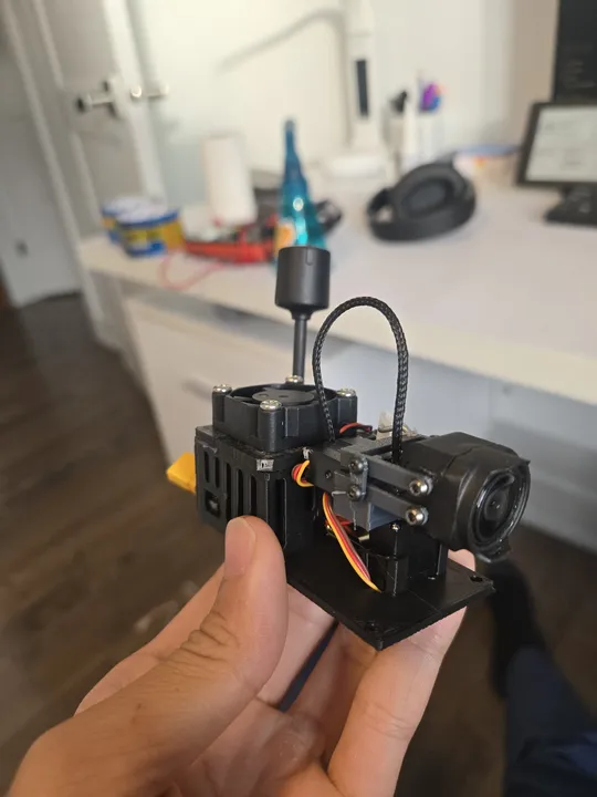 The finished gimbal with the DJI O3 camera mounted.
- On the Goggles: An ESP32 and a gyro sensor to track your head.
- On the Drone: An ESP32 and two servos to move the camera.
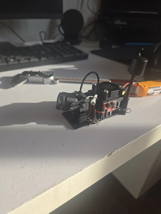 Testing the servos and electronics on the workbench before mounting.
Bill of Materials
The DJI O3 Air Unit is not included — it's shared with the FPV drone builds.
| Component | Cost |
|---|---|
| ESP32-C3 Super Mini × 2 | $2.00 |
| MPU6050 gyro/accelerometer module | $3.00 |
| Micro-servos × 2 (pan + tilt) | $5.00 |
| Switching buck converter | $1.00 |
| Cooling fan (small) | $2.00 |
| 3D printed parts (PLA) | $3.00 |
| Misc (wire, connectors, hardware) | $1.00 |
| Total | $17.00 |
Transmitter Firmware
The goggles-side ESP32 uses the MPU6050's onboard motion processor to compute yaw and pitch, avoiding drift from integrating raw gyro data. On boot it collects 200 motion samples at rest and computes offsets, so the gimbal centers itself regardless of how the goggles are sitting when powered on.
Only yaw and pitch are transmitted — roll is discarded since the gimbal has no roll axis. Each packet carries the two angles, a sequence number, and a checksum. The receiver uses both to reject duplicate, out-of-order, and corrupted packets.
Receiver Firmware
The drone-side ESP32 receives packets, validates the checksum and sequence number, then maps the angles to servo pulse widths. Yaw maps to ±90° pan, pitch maps to ±45° tilt. A 0.5° input deadzone prevents the servos from drifting around center when the head is still.
Servo movement is smoothed with an exponential filter to eliminate jerkiness from discrete angle steps. If no valid packet arrives for 1.5 seconds, the servos return to center automatically, so a lost link doesn't leave the camera pointing at the ground.
The receiver drives the servos directly without going through the flight controller, keeping latency low.
Gyro Drift & Calibration
The biggest challenge was drift. All gyros naturally "drift" over time, making the camera slowly move even if you keep your head still. To fix this, I used a motion processor that fuses gyro data with an accelerometer. The accelerometer uses gravity as a fixed reference to keep the gimbal centered.
I also added a calibration step that runs every time you power it on. It measures the resting position of your goggles so the camera always starts perfectly centered.
3D Model
Files & Links
Built at 15 years 7 months