Electric Bike (v5)

For this version, I decided to fix the "dangerous" charging system once and for all. I moved to a high-voltage 72V system (20S) and bought a professional Daly BMS and a real charger. No more plugging and unplugging wires just to charge the bike.
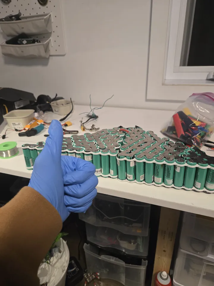
Planning the Pack
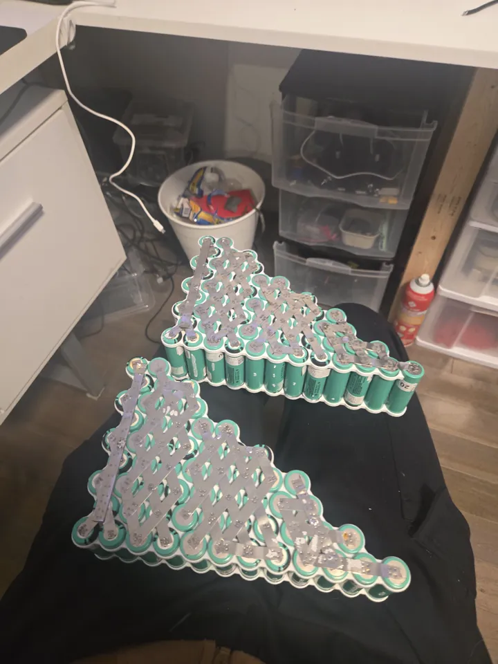
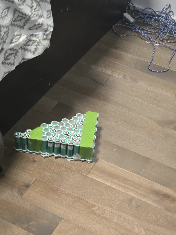
With 120 cells to organize, I used TinkerCAD to plan the layout. It allowed me to color-code the groups and make sure every cell fit perfectly inside the frame.
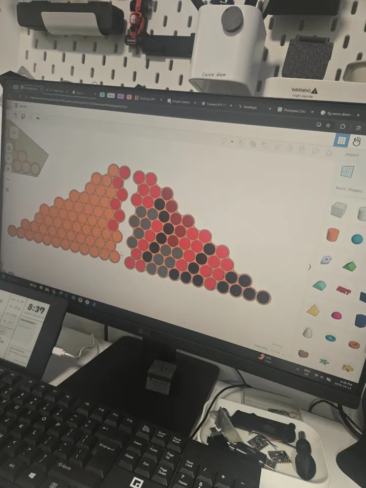 I used different colors for each group of cells to avoid mistakes during assembly.
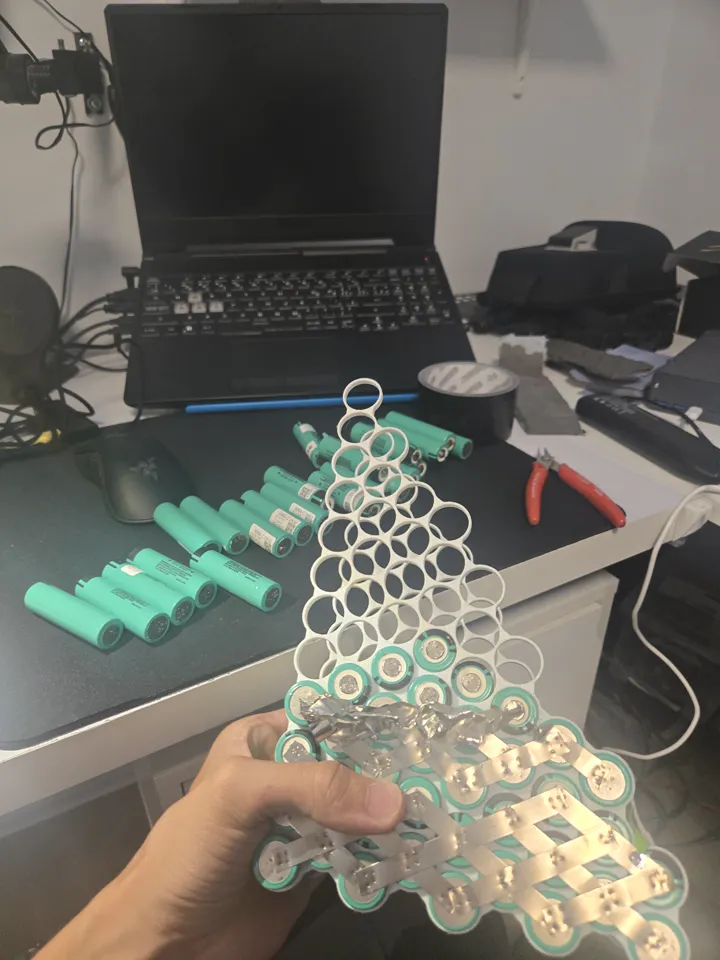
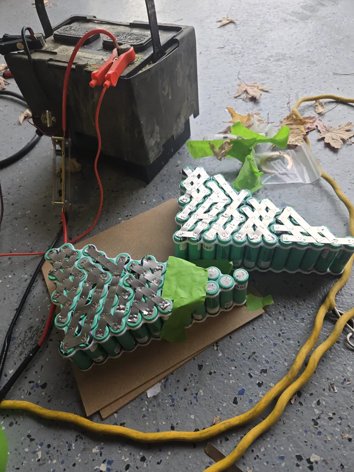
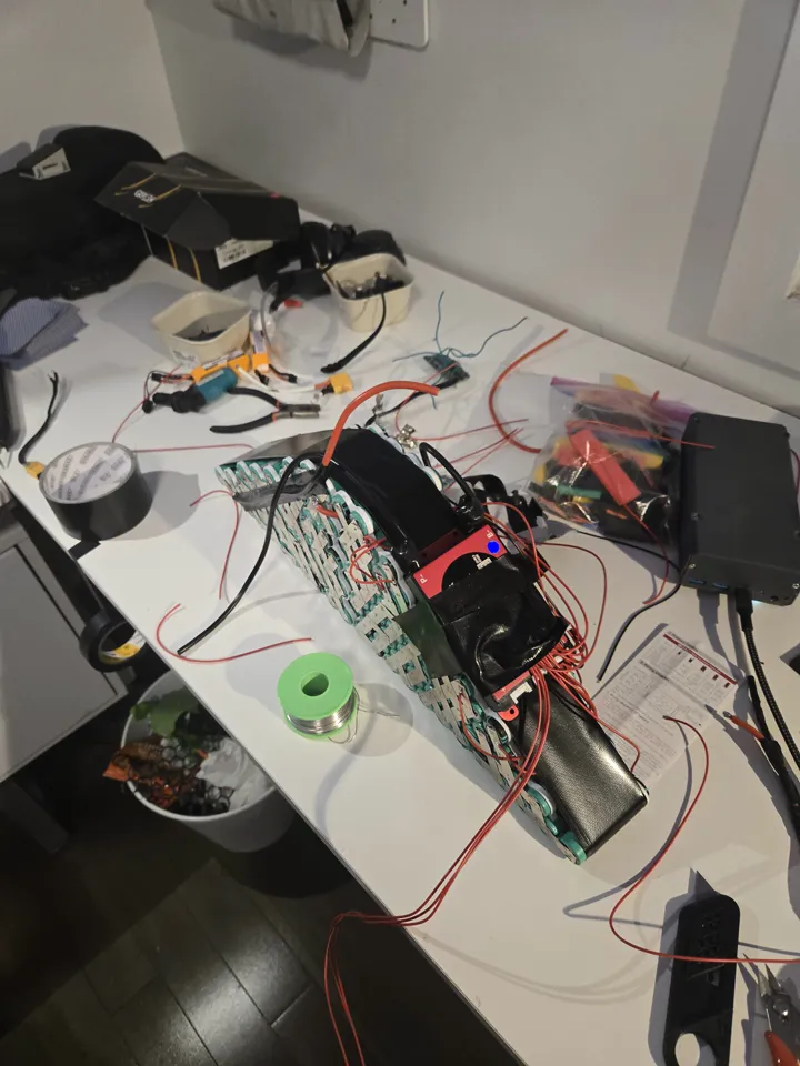
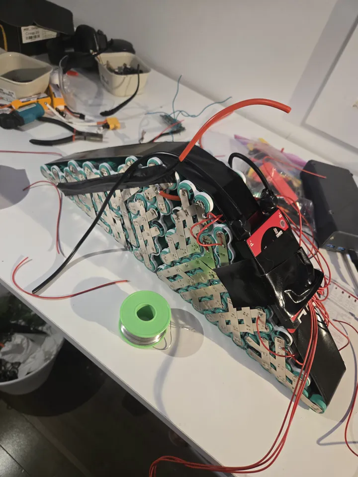
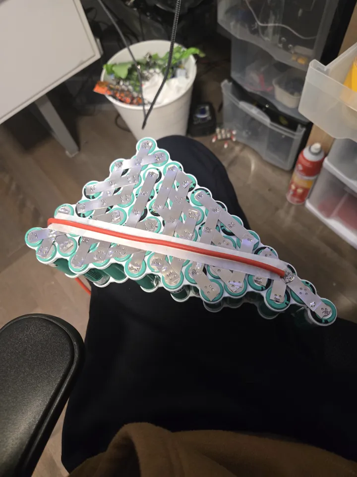
Nickel Strip Layout & Current Density
This was the second time I used CAD to plan nickel strip paths, and the first time I explicitly calculated current density. Previous builds used nickel strips chosen by feel — wide enough to not obviously fail. Here I worked out the cross-section required to carry the expected peak current without the strips acting as fuses.
The two 10S6P halves were connected to each other using 12AWG silicone wire rather than a long run of nickel strip. Long nickel strip inter-pack connections have higher resistance and are mechanically fragile; 12AWG wire is lower resistance, rated for the current, and flexible.
 Inter-pack connections in 12AWG silicone wire — lower resistance and mechanically robust.
Thermal Management
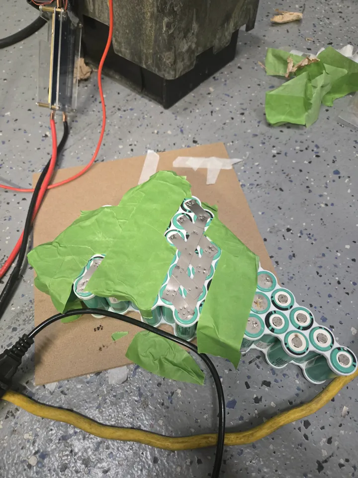
Previous builds wrapped the pack in foam. Foam is an insulator — it traps heat generated by the cells during discharge. v5 uses black tape only, no foam. The cells can dissipate heat directly through the wrap into the air.
BMS & Charging: Ending the Hack
The v4 series/parallel charging workaround existed because the charger could only handle 6S. v5 runs at 20S — 72V nominal, 84V peak — which a 6S charger cannot touch regardless of topology hacks.
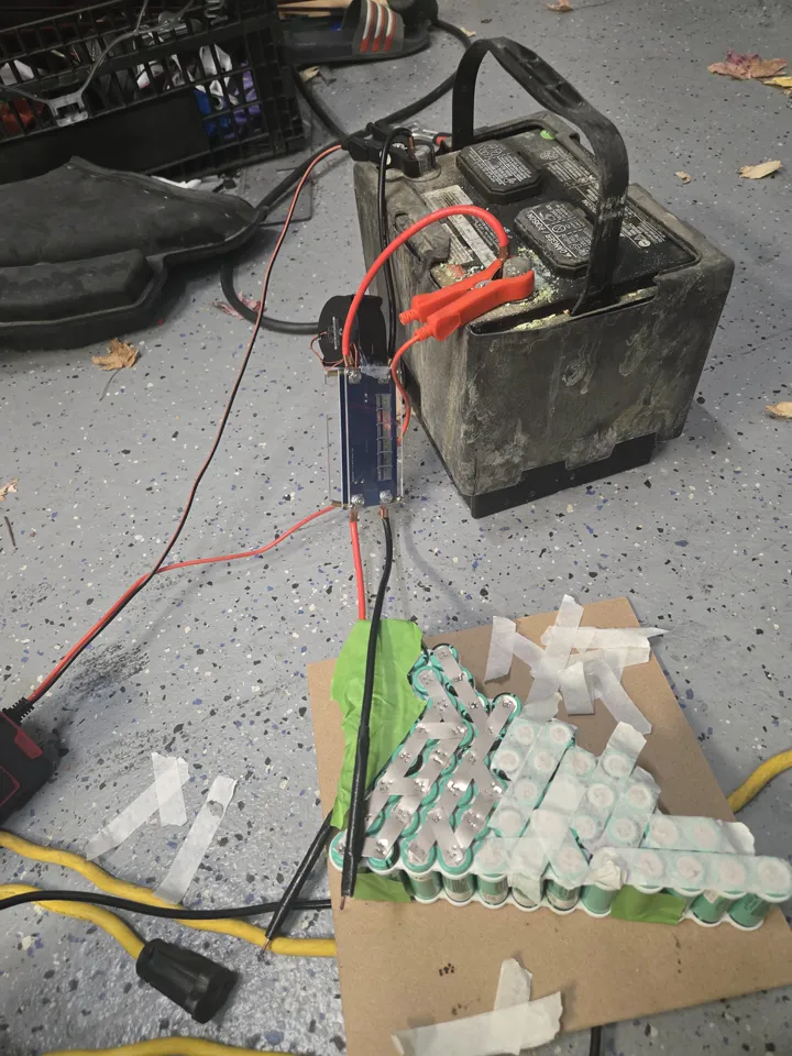
I bought a 40A passive Daly BMS rated for 72V and a matching 2A 72V charger. The BMS handles both charge cutoff and over-current protection properly. The bypass discharge connector is finally gone — the Daly's 40A continuous rating is sufficient for the hub motor's draw without bypassing protection.
Balance leads on a 72V pack are live at potentially lethal voltage across the full string. I wore gloves rated for the work but thin enough to retain tactile feedback for soldering the fine-pitch balance wires.
Lessons Learned
This was the build where I finally understood Internal Resistance (IR). I realized that a battery's health isn't just about how much energy it can hold, but how easily it can give that energy out. If a cell has high IR, it gets hot and loses power.
I also learned that "amateur" habits like using duct tape were bad practice. I switched to Kapton tape, which is the industry standard because it's heat-resistant and doesn't leave a sticky mess.
Bill of Materials
| Component | Cost |
|---|---|
| 40A 72V Daly BMS | ~$45.00 CAD |
| 72V 2A charger | ~$35.00 CAD |
| Nickel strips + 12AWG wire | ~$20.00 CAD |
| Black tape + misc hardware | ~$10.00 CAD |
| Cells (recycled from v4) | — |
| Hub motor + VESC (carried from v4) | — |
| Total new spend | ~$110.00 CAD |
Built at 16 years 7 months