Electric Bike (v4)
Building the Wheel
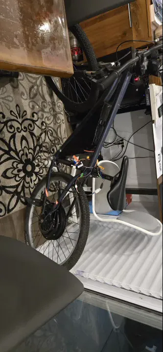
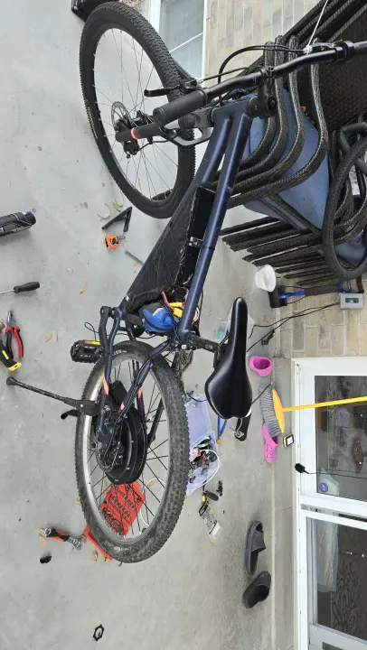
For this version, I moved to a "hub motor" system. This means the motor is actually part of the rear wheel itself. Since I bought just the motor, I had to learn how to "lace" it into a rim using metal spokes.
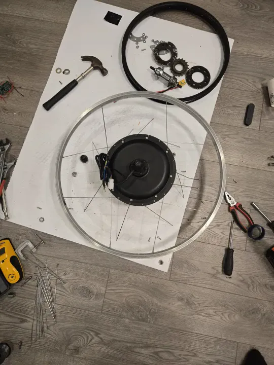 Learning how to lace a wheel. It took a full day and several tries to get the tension right.
It was a slow, frustrating process, but eventually, I had a working 2000W wheel that could push the bike much faster.
The Dual-Battery "Hack"
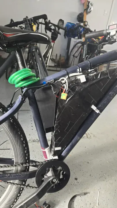
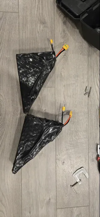
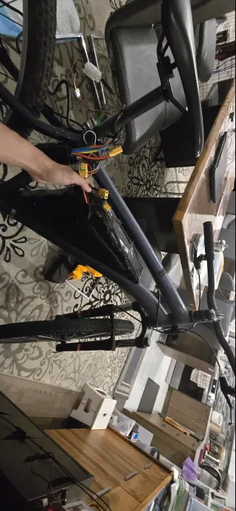
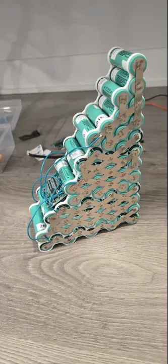
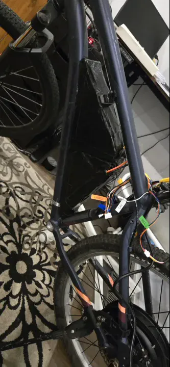
I built two separate 22V (6S) battery packs. To ride, I plugged them together in "series" to get 44V (12S). To charge, I unplugged them and plugged them together in "parallel" so I could use a cheaper 22V charger.
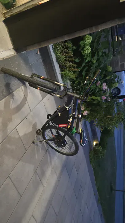 Notice the "Remove Before Flight" tag—I added that after a wiring mistake almost caused a fire during charging.
One day, I accidentally plugged the batteries in the wrong way and saw actual sparks. I destroyed two safety boards (BMS) before I learned to be more careful.
This required a manual switching step between modes. Each pack had its own $6 BMS for charge protection. For discharge I used the bypass trick from v2: a second output connector that goes around the BMS entirely so the full current hits the VESC without restriction.
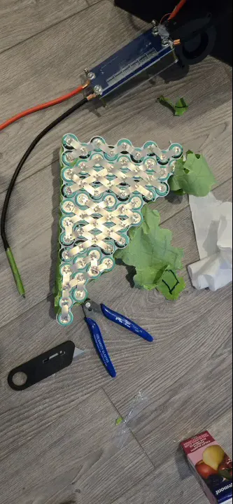
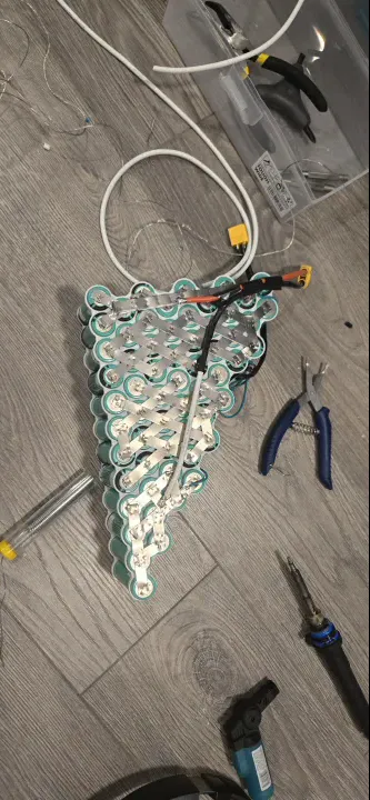
I used a Sharpie on green painter's tape to diagram the cell connections before spot welding — a system that worked well for keeping track of the series/parallel topology during the weld sequence.
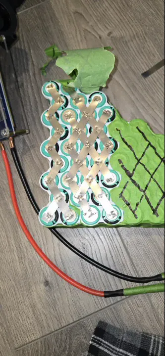 Sharpie on painter's tape — wiring diagram drawn directly on the pack before welding.
The Short Circuit
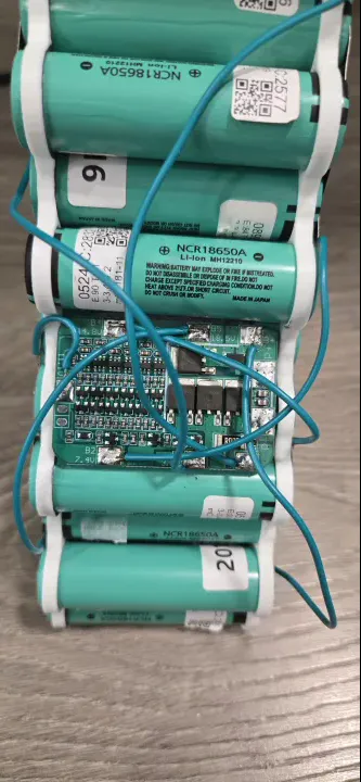
I plugged in the parallel charge connector while the series key was still connected. This created a dead short across both BMS units simultaneously — enough current to destroy them both instantly. Two $6 BMS units, both gone in one mistake.
The root cause is a logic problem: the series and parallel states are mutually exclusive, but there was no physical enforcement of that constraint. Both connectors were accessible at the same time. For v5 this would need an interlock — either mechanical keying or a relay that physically disconnects series before parallel charging is possible.
After replacing the BMS units, I conformal coated both boards for water resistance and added a "remove before flight" tag on the series key connector so I could not miss it before plugging in the charger.
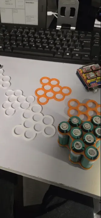
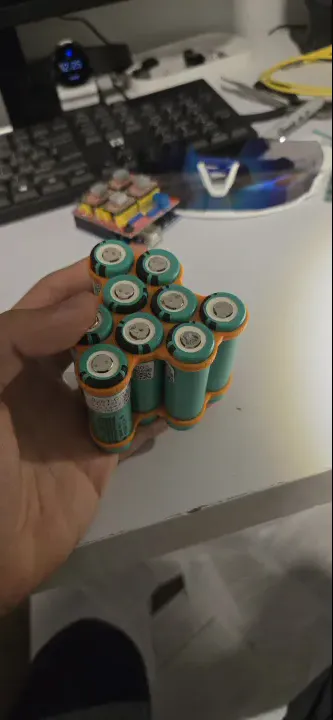
3D Printed Battery Mounts
I printed tolerance-test iterations of the battery mount before committing to the final part. The mount held mechanically but PLA is brittle — it cracked under vibration and impact over time. This was the build that confirmed for me that PLA is the wrong material for any structural frame component on a vehicle. PETG or ASA for anything that takes load or vibration; PLA only for static brackets.
VESC Enclosure
The VESC started in a soft bag strapped to the frame. I later designed and printed a cover with airflow passages to keep it cooler under sustained load.
Conclusion
This bike was very fast but the charging system was too complicated. Every time I wanted to charge, I had to play with a bunch of wires. It was a great learning experience, but it proved that I needed a better way to handle high-voltage batteries.
Bill of Materials
| Component | Cost |
|---|---|
| 2000W Hub Motor | ~$300.00 CAD |
| 26-inch rim (for lacing) | ~$30.00 CAD |
| 18650 cells | ~$50.00 CAD |
| 2× BMS (destroyed + replaced) | ~$24.00 CAD |
| VESC (carried from v3) | — |
| 3D print filament + misc | ~$15.00 CAD |
| Total new spend | ~$419.00 CAD |
Built at 16 years 3 months