Electric Bike (v3)
By age 15, I wanted the bike to have more torque. Instead of the motor spinning the tire directly, I built a "mid-drive" system that used a chain and sprocket. This meant the motor could help the bike climb hills much better.
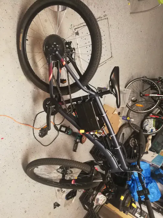 The finished v3 model. You can see the large motor and the chain drive system.
Drivetrain & Gearing
I removed the pedal chain entirely and mounted a 10-tooth sprocket on the 6384 outrunner motor, driving the stock 33-tooth rear wheel sprocket. That gives a 3.3:1 reduction. At 120KV and 6S (roughly 22V), the motor spins at around 2640 RPM at no load, which drops to a usable wheel speed around 45 km/h once the reduction is applied.
The gears were cheap Chinese chainrings sourced online. They worked, but the chain tension was never stable because of the mount.
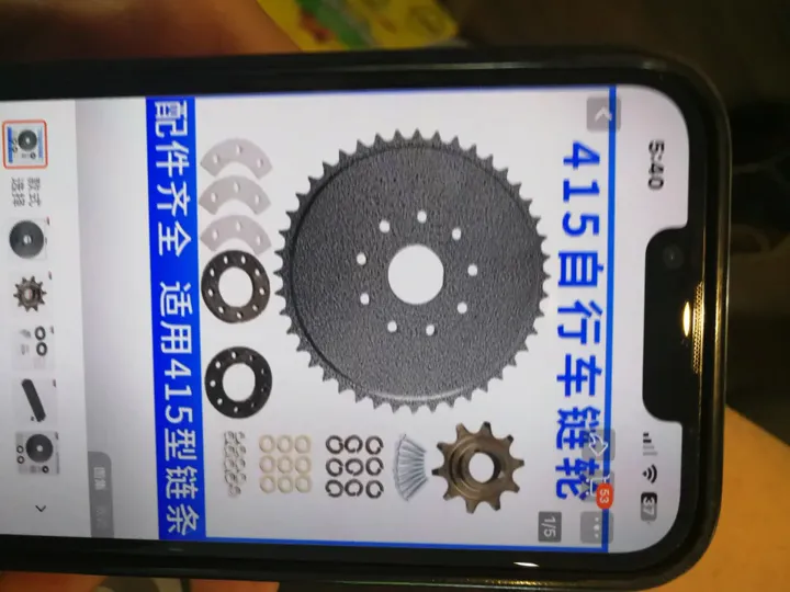 10T motor sprocket to 33T rear — 3.3:1 reduction.
Motor Mount
The motor was attached to the frame using the water bottle cage mounts as anchor points, plus hardware store L-brackets. To clamp the L-brackets securely to the frame tubes, I cut a groove in each bracket and threaded a metal screw tie through it, then cinched it around the tube. It held, but it was not rigid under dynamic torque — the brackets still deformed over time.
For the first time I also used rivnuts. I had no proper rivnut tool, so I fabricated a contraption from whatever hardware I had at hand to pull the mandrel and set them. It worked well enough to be a permanent fixture. The rivnuts gave me threaded inserts in the frame without welding, which was the right call given the tools available.
I also modeled up a 3D-printed PLA bracket for the battery tray from the frame fitment reference photo, and mounted the VESC at the front of the frame.
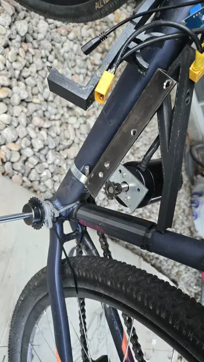 Motor mount, PLA battery tray, and VESC visible. Functional, barely.
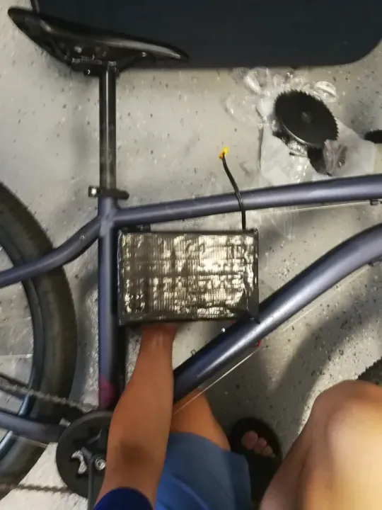 Photo used as reference geometry for the 3D printed bracket.
My First Spot Welder
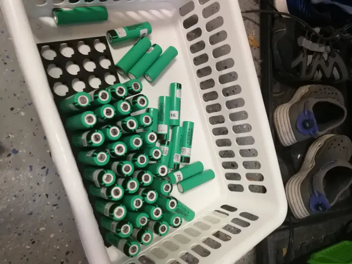
I also finally stopped soldering directly to battery cells. I bought a cheap battery spot welder from AliExpress. This uses high-current pulses to fuse a thin nickel strip to the cell without heating up the entire battery.
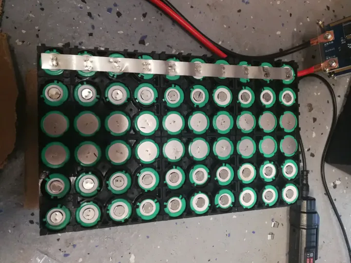 Learning how to spot weld. It's much safer and more reliable than soldering.
It took some practice to get it right, but this was a huge step toward building professional-quality battery packs.
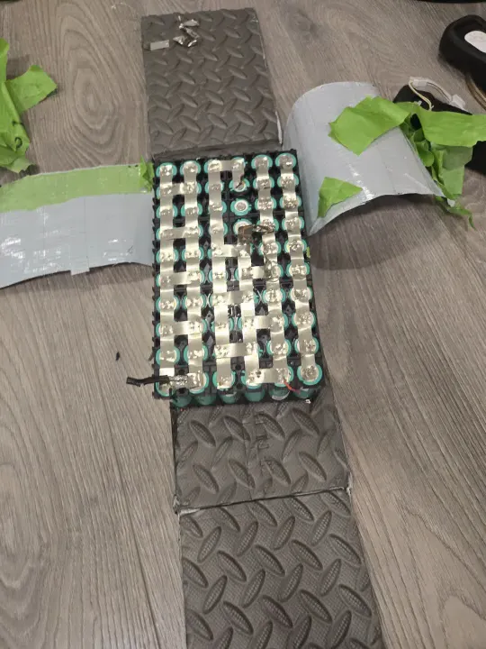
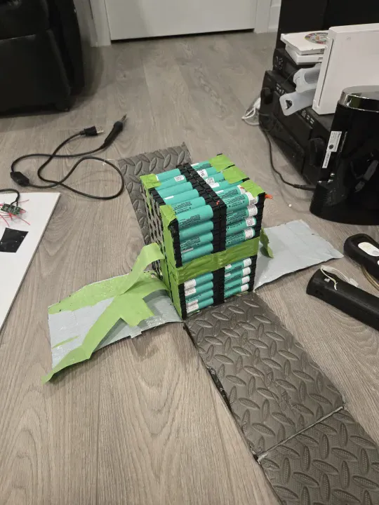 Pack interior — foam padding and duct tape, consistent with the v1/v2 build standard.
Dashboard
Before adding the BLE bridge, I built a local dashboard: a 0.91-inch OLED wired to an ESP32, displaying speed, battery voltage, and SOC in real time. I knew voltage alone tells you the state of charge on a lithium cell when the pack is at rest — voltage under load is a different story, but for a rough fuel gauge it was sufficient.
The OLED was the reason the first VESC died. While wiring the ESP32 to the VESC UART connector, I accidentally shorted a data pin to ground. That was enough to kill the BEC. Not a component quality failure — a wiring mistake. It was only after I replaced the VESC and looked more carefully at what happened that I understood the root cause.
BLE Telemetry
For the first time, I added real-time telemetry. I flashed an open-source project — VescBLEBridge — to an ESP32, which bridges the VESC UART output to Bluetooth Low Energy. This let me read voltage, speed, and current from my phone while riding. First time using PlatformIO and VSCode for an ESP32 project (I had used PlatformIO before at 13 for flashing Klipper to an Ender 3, but this was different — compiling and uploading actual firmware logic, not just a config).
VESC Failures
This build killed two VESCs:
VESC #1 — same 75100 model, bought cheap. The internal BEC failed. The actual cause was my own fault: while wiring the OLED ESP32 to the VESC UART, I shorted a data pin to ground and killed the BEC. I did not realize this at the time and assumed it was a component failure.
VESC #2 — same result. Different unit, same failure. At this point two identical controllers failed in identical ways on identical hardware, which means the budget 75100 BEC is the weak link, not my wiring or setup.
VESC #3 (current) — sourced from a more reputable seller at 75. In all other functions it works correctly. You get what you pay for.
Bill of Materials
| Component | Cost |
|---|---|
| 6384 Outrunner 120KV | ~$40.00 CAD |
| VESC 75100 ×2 (both failed) | ~$120.00 CAD |
| VESC 75100 (reputable seller) | ~$75.00 CAD |
| Chainring + 10T motor sprocket | ~$20.00 CAD |
| L-brackets + hardware | ~$10.00 CAD |
| 18650 cells (~$1 each) | ~$50.00 CAD |
| ESP32 + misc | ~$10.00 CAD |
| Total | ~$325.00 CAD |
The Cost of Failure
This build was a hard lesson in power electronics. I managed to burn out two expensive VESCs. The second one failed when I tried to go up a steep hill while the motor was still cold. The sudden spike in current was too much for the controller.
In the end, this version reached 45km/h, but it was often broken. It taught me that building a powerful bike is much harder than just making a fast one.
Files & Links
Built at 15 years 5 months