Electric Bike (v2)
After the first motor controller failed, I bought a VESC 6.7 Pro. This was the first time I spent real money on a single part ($120). It made the motor run much smoother and even allowed the bike to charge itself slightly when braking (regenerative braking).
The BMS Bypass
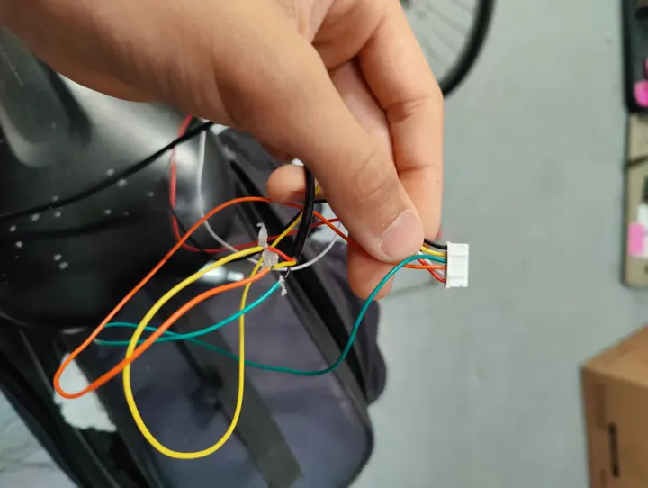
In the first version, the battery safety board (BMS) kept burning out because I was pulling too much power. To fix this, I rebuilt the battery with two plugs. One plug went through the BMS for safe charging, but the other plug went straight to the motor, bypassing all safety.
 One plug is for charging, the other provides raw power directly to the motor.
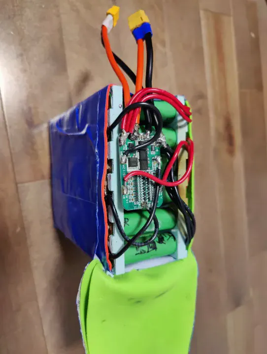
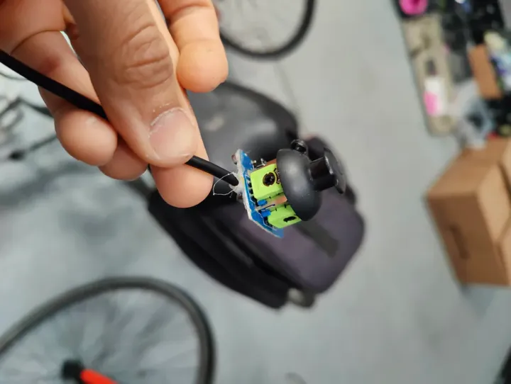
This was a bad idea. It meant there was no protection if something short-circuited. I knew it was risky, but I wanted the bike to be fast. I also saw that the original BMS had actual scorch marks from where it failed.
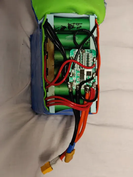 The first BMS couldn't handle the current and started to melt.
VESC Configuration
First time using a VESC. I set battery max current to 40A, motor current to 40A, and left most other settings at their defaults after reading what each parameter actually did. The VESC handled the motor cleanly and gave regenerative braking — a huge step up from the RC ESC, which just cut power and coasted.
I spent a day on this. By end of day I understood current limits, duty cycle control, ADC input modes, and why RC ESCs fail in this application (they are tuned for propeller loads, not motors that stall, reverse, and experience high inertia).
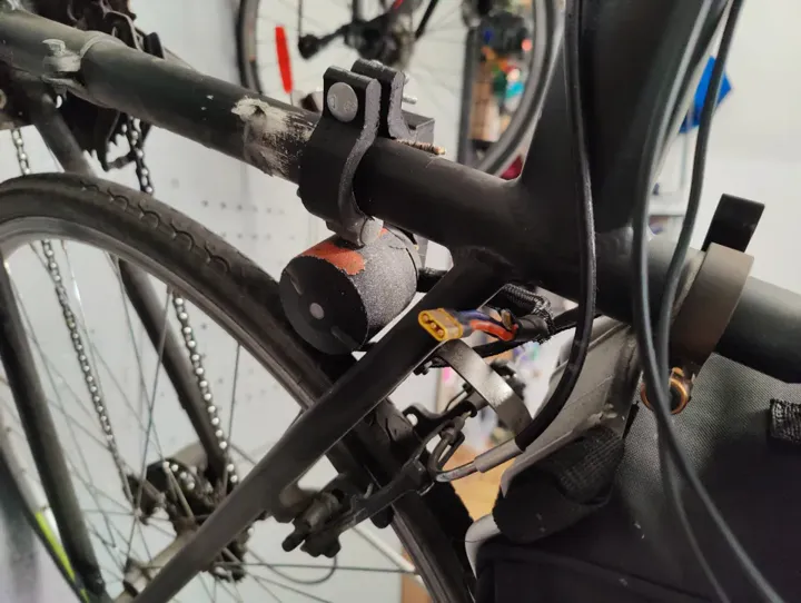
Magnetic Throttle
I also redesigned the throttle. I used a small joystick module and hot-glued magnets to the bottom. I then glued magnets to the handlebars so the joystick could snap on and off instantly.
 The magnetic mount made it easy to take the throttle off when I parked the bike.
Performance and the McGill Expo Ride
Top speed was around 40 km/h. I had no display or watt meter, so I carried a multimeter in my bag on the rear rack and checked resting cell voltage by hand when I stopped.
I rode to the McGill Engineering Expo that summer — 20 km from the South Shore, crossing the bridge. Got there with the pack sitting at roughly 3.5V per cell — close enough to the 3.0V low-voltage cutoff that I stopped and did not push further. At the expo, I tried asking the engineering department if I could borrow a DC bench supply to charge my pack to exactly 25.2V (4.2V/cell × 6S). Nobody took me seriously. I was 13.
Bill of Materials
The only new cost on this build was the VESC — everything else carried over from v1.
| Component | Cost |
|---|---|
| VESC 6.7 Pro | ~$120.00 CAD |
| Joystick throttle module | ~$10.00 CAD (salvaged) |
| Magnets + epoxy | ~$5.00 CAD |
| Total new spend | ~$135.00 CAD |
Post-Mortem
The friction drive was the mechanical weak point. I was constantly re-tensioning the motor against the tire. This was worsened by PLA Creep: the main motor holder was 3D printed in PLA and held under constant tension to keep the motor pressed against the wheel. PLA deforms under sustained load over time. I realized this too late, and it served as a permanent lesson to never use plastic for structural, high-tension motor mounts. I upgraded to metal and never went back.
Around the same time, the VESC failed—specifically the internal BEC (Battery Eliminator Circuit). I never found out why it broke. As a 13-year-old with a $10 soldering iron, I tried to fix it myself after being ignored by a micro-soldering guy on Facebook Marketplace. Predictably, trying to do micro-soldering on a high-density PCB with a cheap iron just ruined the traces. The VESC was eventually scrapped.
The battery remained the biggest risk — and looking back, the BMS bypass was a genuinely bad idea that I would not repeat. At the time, my only experience with batteries was LiPo packs with balance leads. With a balanced, fully charged LiPo pack, you can discharge to around 10% without meaningful cell drift — the cells track each other closely when they start in balance. That was my mental model here: if the pack was charged and balanced, I just needed to avoid a dead short and not over-discharge. I did not yet understand that a purpose-built battery pack from salvage cells with hand-soldered copper bus bars and no individual cell monitoring was a fundamentally different risk category. I did not fully internalize why that distinction mattered until around v4-v5.
The wiring made it worse. I bought cheap PVC-insulated wire from a local hardware store. PVC insulation starts to soften and melt around 60–70°C, and at 40A it was clearly running warm. The insulation was visibly deforming on longer rides. Silicone wire handles heat properly; PVC does not. That was a fire risk I did not even know I was carrying.
Built at 14 years 0 months