Electric Bike (v1)
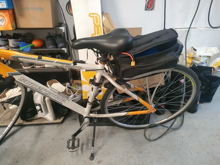
I built this bike when I was 13. I didn't have a lot of money, so I used a "friction drive" system. This means the motor sits directly on the tire and spins it using a piece of sandpaper tape.
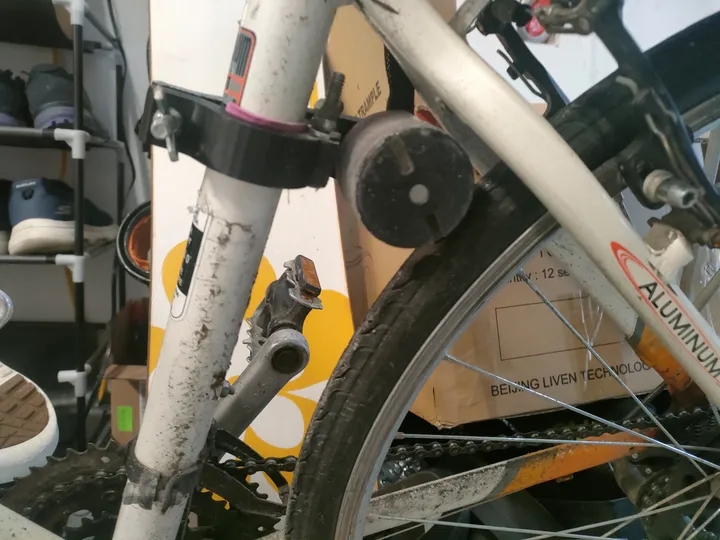 Sandpaper tape on the motor provides grip against the rubber tire.
It wasn't very efficient and the tape wore out quickly, but it was the easiest way to make the bike move without a chain or gears.
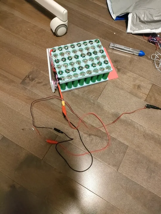
Hand-Soldered Battery
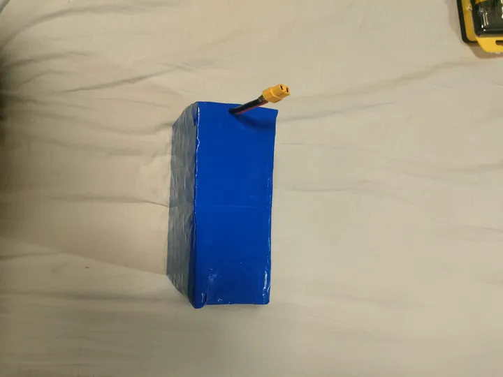
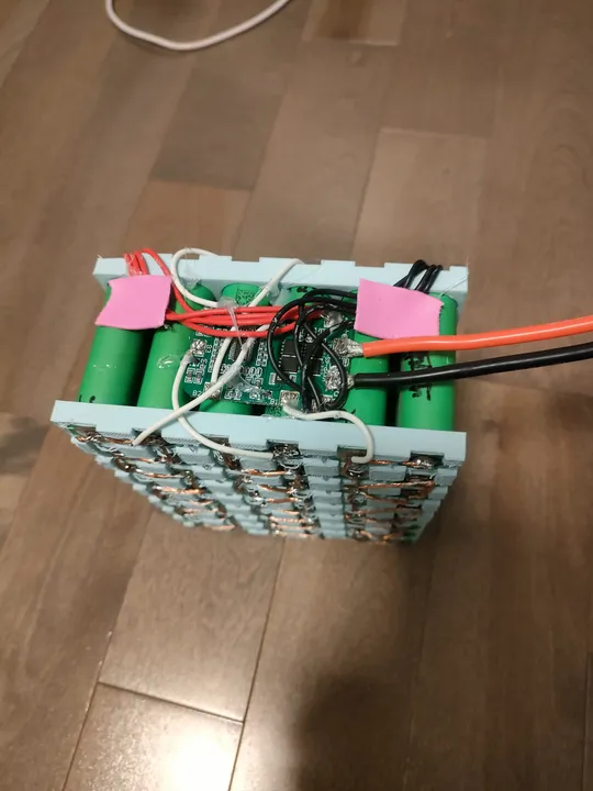
The battery was my first big electronics challenge. I used 48 individual 18650 cells that I bought from the Facebook Marketplace. Since I didn't have a spot welder, I soldered thick copper wires directly to the cells.
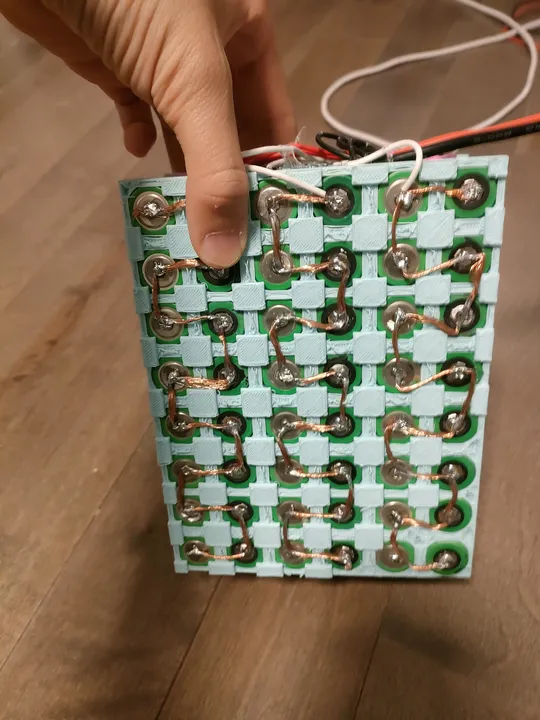 I used thick copper wires from an old extension cord to connect the cells.
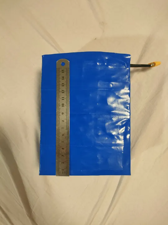
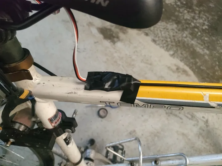
This was a dangerous way to build a battery because the heat from the soldering iron can damage the cells. I wrapped the whole thing in foam and blue duct tape to keep it together.
Conclusion
The bike worked for a few weeks, reaching about 20km/h. Eventually, the cheap motor controller (ESC) burned out because it wasn't meant to handle the high current needed to start the bike from a stop.
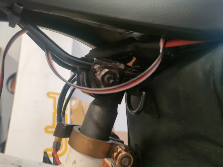
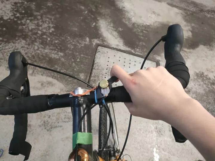
Throttle
The ESC needed a PWM signal in the standard RC range. A potentiometer outputs analog voltage. I could not find a ready-made adapter, so I wired a cheap pot into an Arduino Nano and wrote a short sketch to read the ADC and output a mapped PWM signal on a servo pin. The Nano ran off the ESC's BEC.
 Arduino Nano reading the pot and outputting PWM — powered from the ESC's built-in 5V BEC
The throttle body itself was 3D printed, with a small lever sized for one finger.
What Came Next
After the ESC died, my dad got me a VESC 6.7 Pro. That became v2 — a much more reliable build that I actually rode for a full year and took on longer trips.
The CAD files for the printed parts are probably gone. The machine I was printing on at the time had no remote backup and no Klipper, so nothing was saved. I have not been able to find them.
Built at 13 years 11 months