Global Project Export (LLM Friendly)
Formatted specifically for LLMs. Hierarchical grouping by tiers with ongoing projects prioritized at the top.
# HABANERO CHEESEBURGER PORTFOLIO
Generated: 2026-05-03T00:12:53.302Z
Total Projects: 41
## ONGOING & ACTIVE BUILDS
Current engineering focus and active development.
### SafeReps — Marihacks IX
Date: 2026-04-18 (Age: 17)
Tier: 2
Category: HARDWARE & SOFTWARE
Description: A dual-stream coaching system that fuses phone-based computer vision with a custom wrist wearable to detect form breakdown, momentum cheating, and neuromuscular fatigue in real time. Got honorable mention for the design track.
GitHub: https://github.com/StudentBroken/SafeReps
External Links: View on Devpost (https://devpost.com/software/safereps)
[CONTENT]
# SafeReps — Marihacks IX
SafeReps is a dual-stream coaching system built for home strength training. A Flutter app tracks 33 skeletal landmarks via Google ML Kit at 30 FPS, while a custom wrist wearable samples a 6-axis IMU at 100 Hz and streams the data over BLE. The two feeds are timestamp-aligned on-device, feeding a rep state machine that classifies every repetition for range of motion, momentum cheating, and neuromuscular fatigue. When a violation is detected, a priority-gated voice coach fires the relevant correction in real time.
Built at MariHacks IX in approximately 15 hours — hardware assembly, firmware, app, and pitch deck included. The team was two people; my partner was relatively new to both hardware and software, so a significant portion of the build time also involved teaching and pair programming rather than just heads-down development.
## Tech Stack
| Layer | Technology |
|---|---|
| Mobile app | Flutter + Google ML Kit (pose landmarks at 30 FPS) |
| Wearable MCU | ESP32-C3 with BLE |
| Motion sensor | MPU6050 6-axis IMU at 100 Hz |
| DSP | On-chip high-pass filter + angular/linear velocity ratio |
| State machine | 5-stage FSM: Idle → Top → Descending → Bottom → Ascending |
| Voice coach | Priority-gated audio engine with Fisher-Yates shuffled cue pools |
| Calibration | 1-second T-Pose routine for automatic sensor-to-limb alignment |
## Hardware
The prototype BOM comes in under \$5, with a custom PCB at volume projected to drop it to ~\$3.
- **ESP32-C3** — logic and low-latency BLE connectivity
- **MPU6050** — 6-axis IMU, sampled at 100 Hz
- **400 mAh LiPo** — runtime of 12+ hours of active use
- **USB-C charge module** — integrated charging
- **Protection circuit** — 100 kΩ voltage divider for battery monitoring; diode and capacitor for transient protection
## Core Intelligence
### Rep State Machine
A 5-stage FSM governs every set: Idle → Top → Descending → Bottom → Ascending. State transitions are gated on joint angles crossing calibrated thresholds derived from the T-Pose calibration, so a rep is only counted when it reaches anatomically complete range of motion.
### On-Chip DSP
The ESP32-C3 runs two signal processing routines before sending data to the phone:
- **Tremor analysis** — a 100 Hz high-pass filter isolates neuromuscular jitter from intentional movement. Persistent jitter above threshold is flagged as a fatigue indicator before the user consciously feels it.
- **Cheat detection** — the ratio of angular velocity to linear acceleration distinguishes clean muscle contraction from momentum-driven swinging.
### T-Pose Calibration
A 1-second T-Pose at the start of each set performs two alignment steps: sensor zeroing (synchronizing wearable orientation to the skeletal model) and scaption alignment (correcting for mounting tilt against the user's specific limb geometry). This eliminates the need for any manual setup.
### Voice Coach
The audio engine uses priority gating so corrections always interrupt encouragement, never the other way around. Cue pools are shuffled with Fisher-Yates so the same phrase does not repeat until the entire pool has played through.
## Latency
The most significant engineering constraint was coaching latency. A cue that arrives 500 ms after a form violation is too late to be useful. The sensor-to-coach pipeline — BLE transfer, timestamp alignment, FSM evaluation, and audio dispatch — was optimized to fire corrections within milliseconds of detection.
---
### Electric Bike (v6)
Date: 2026-04-16 (Age: 17)
Tier: 1
Category: HARDWARE | Series: Electric Bike
Description: The current pinnacle of the series: Grade-A EVE 33V cells, rigorous validation with 4-wire IR and capacity testing, and a unibody PETG battery holder. A professional-grade build with a 2500W peak output and a perfectly matched internal resistance spread.
[CONTENT]
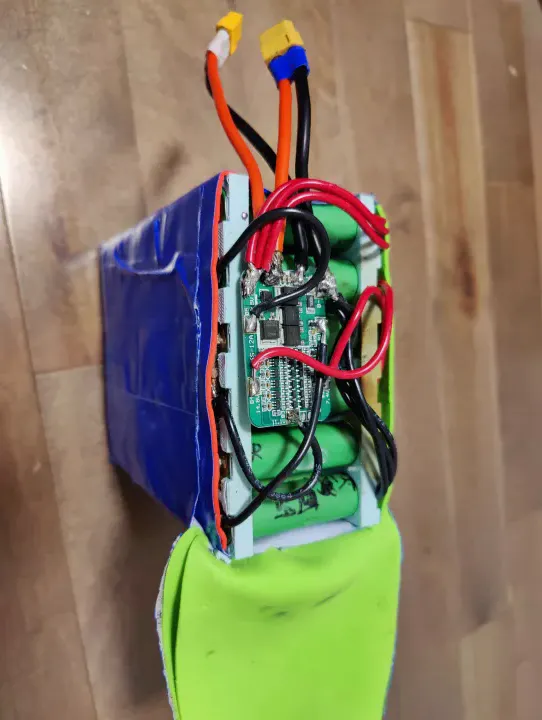
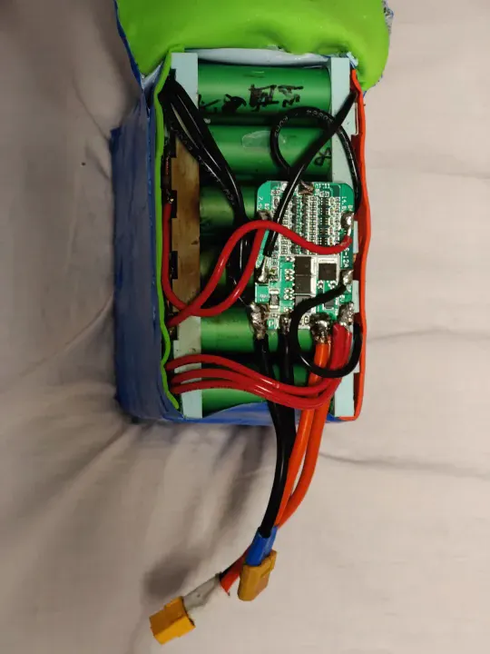
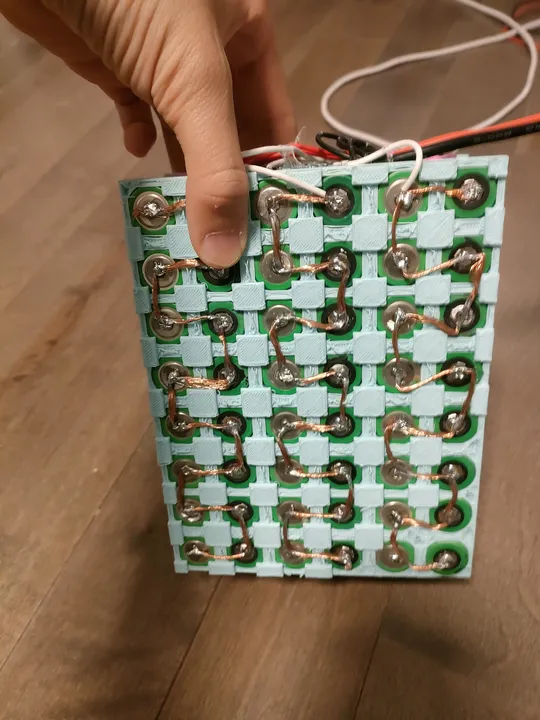
# Electric Bike (v6)
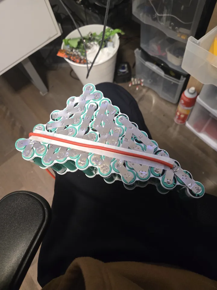
At age 17, I built this bike to be the perfect version of all my previous builds. Instead of using old, recycled cells, I bought 100 brand-new **EVE 33V** cells. I tested every single one to make sure they were all identical in health and power.
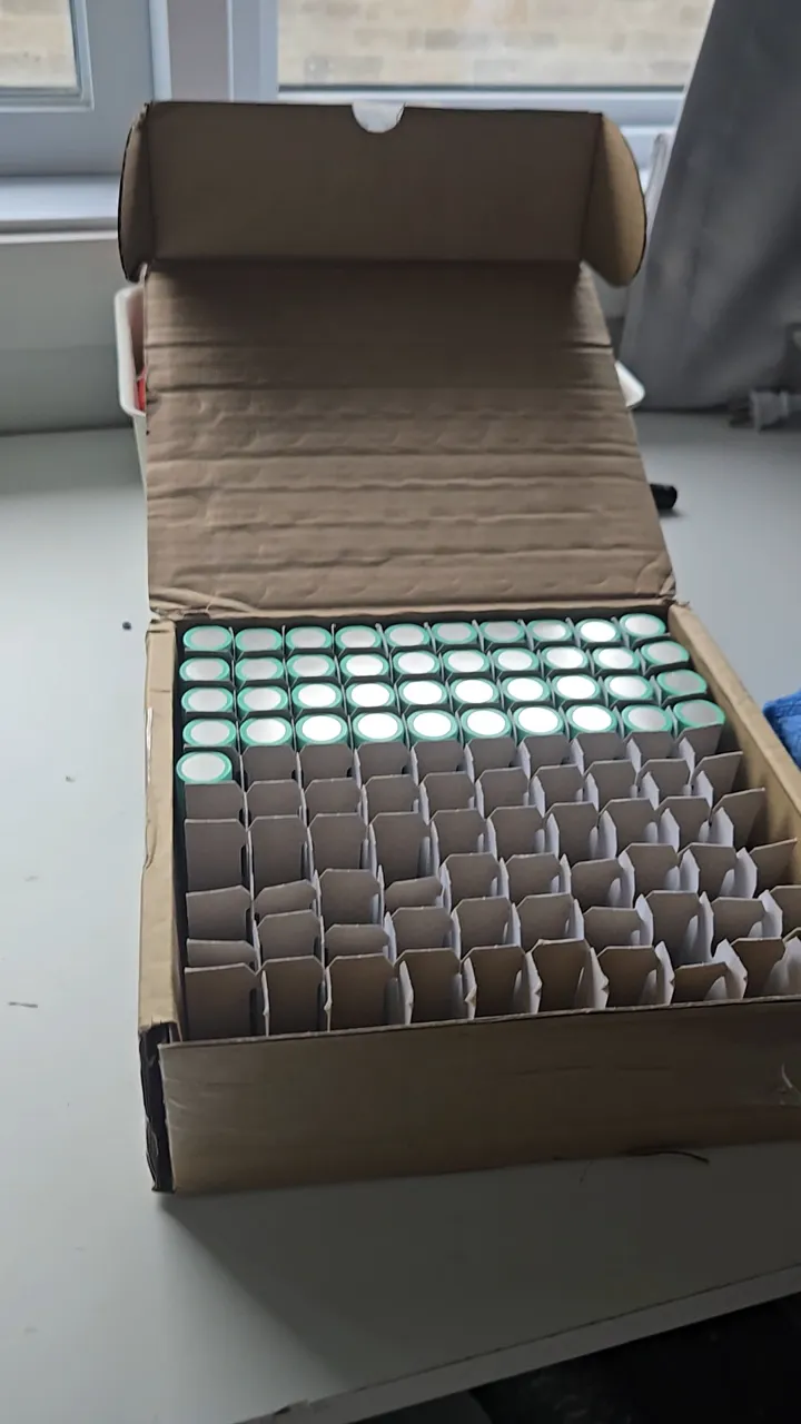
*I bought 100 Grade-A cells to ensure the battery would last for years.*
This is the fastest and most reliable bike I've ever built. It can reach 65km/h and doesn't lose power even when climbing steep hills.
## Professional Grade Construction
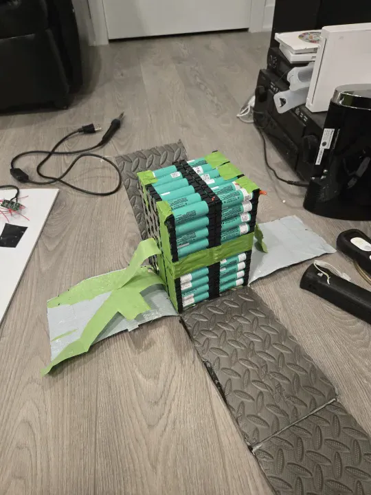
I stopped using glue and tape to hold the battery together. Instead, I designed a "unibody" holder that was 3D printed in **PETG** plastic. PETG is much stronger than the PLA I used before and can handle the vibrations of the road without cracking.
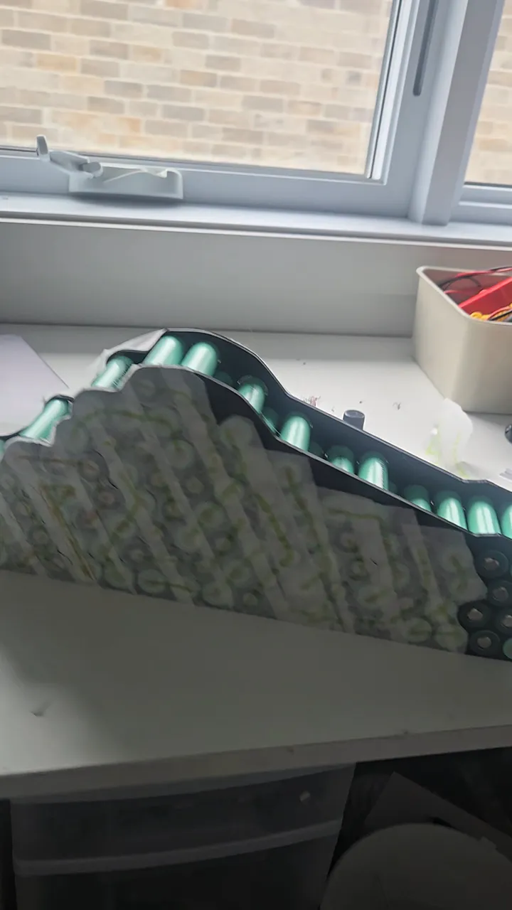
*Unibody PETG holder — 20S5P alignment. PETG was selected for its superior impact resistance over PLA.*
## Electrical Architecture & Load Calculation
The system is designed for a peak output of 2500W. Even when over-currenting the ESC to 100A during hard acceleration, the cells only hit 60–85% of their maximum continuous discharge rating. Designing with this overhead ensures longevity and prevents the thermal runaway risks seen in v1-v3.
For the nickel strips, I moved away from "estimated" sizes to explicit math. I used 8mm x 0.2mm pure nickel strips, which have a cross-sectional area of 1.6mm² and a rated capacity of 14A continuous. Each series bridge (cathode of group A to anode of group B) uses at least three of these bridges, providing a total cross-sectional area of 4.8mm² and 40–45A of continuous capacity. With a realistic peak draw of ~35A, the interconnects operate well within their thermal limits.
I also accounted for path length and mechanical stress:
- **IR Compensation**: Long-reach connections used double nickel strips to minimize voltage drop and internal resistance.
- **Stress Relief**: Added a minor amount of slack in the nickel bridges to compensate for thermal expansion and frame vibrations, preventing spot-weld failure over time.
For the lacing and cutting, I used a custom stencil to ensure every piece was identical, maintaining uniform current density across the entire pack.
## Insulation & Safety
The insulation strategy is multi-layered:
- **Primary**: Kapton tape for high-heat electrical insulation.
- **Secondary**: Multiaxial Fiberglass tape for structural reinforcement and additional puncture resistance.
- **Final**: The pack is housed in a rigid PETG outer shell.
## Conclusion
The biggest lesson from five years of building ebikes is that you can't build a professional machine with bad materials. Using brand-new cells and proper engineering math made this bike faster, safer, and much more fun to ride.
## Bill of Materials
| Component | Cost |
|---|---|
| 100x EVE 33V Grade-A cells | ~$450.00 CAD |
| BMS Daly 72V 40A (same as v5) | ~$45.00 CAD |
| PETG Filament (unibody holder) | ~$10.00 CAD |
| Kapton + Fiberglass + Nickel | ~$10.00 CAD |
| **Total** | **~$515.00 CAD** |
---
### RepGate — Exercise for Screen Time
Date: 2026-04-13 (Age: 17)
Tier: 1
Category: SOFTWARE
Description: A cross-platform parental control app where children earn screen time by completing verified exercise sessions. In App Store review as of April 2026.
External Links: Waitlist (https://repgate.app)
[CONTENT]
# RepGate — Exercise for Screen Time
RepGate is a cross-platform parental control app built in Flutter. The core mechanic is simple: a child completes a verified exercise session, and the app unlocks a set amount of screen time. Parents configure the rules — exercise type, duration, credit ratio — and RepGate enforces them through native OS APIs on both platforms. It has been in active development since November 2025 and was approved by Apple as of May 2, 2026, as the first app version submitted to them.
## Exercise Verification
The app uses your phone's camera and AI to count reps in real time. It tracks your joints—like hips and knees for squats—to make sure you're doing the exercise correctly. All of this happens directly on your phone; no video or private data is ever sent to the internet.
*RepGate uses on-device AI to count reps without sending video to the cloud.*
To prevent cheating, the app takes a random photo during each set. Parents can check these photos later to make sure the workout was real. The photos are low-resolution to keep things private.
RepGate also works with Strava. If you already track your runs or bike rides there, the app can import them and give you screen time credits automatically.
The app also supports Grease the Groove: short, frequent mini-sessions spread across the day rather than one long block. A Coach can schedule these at fixed intervals, and each mini-session awards a partial credit that accumulates toward a screen time unlock.
## Native Screen Time Integration
On iOS, RepGate uses Apple's official "FamilyControls" to block and unblock apps. This is the most complex part of the app. I even sketched out how the background processes would communicate on the back of a math exam because I couldn't stop thinking about it.

*I sketched the entire background logic on the back of a math midterm—December 19.*
The app has to talk to a separate, hidden "extension" that stays running even if you close the app. They share data through a secure container so they always know how much time is left.
### Three Blocking Modes
Apps are only unblocked when three independent flags are all false. They stack:
- **Usage limit** (`isBlockActive`) — set by the extension and ScreenTimeManager when the kid runs out of earned screen time.
- **Sleep mode** (`isSleepBlocked`) — set by the extension when a bedtime schedule fires.
- **Calendar strict** (`isStrictBlocked` / `calendarStrictConfig`) — fires for scheduled activities (run, swim, cycle). The shield color varies by activity type: Crimson, Ocean, or Forest.
- **Task strict** (`isStrictBlocked` / `strictActivityLabel`) — fires when a Coach assigns a remote task. Shield color: Deep Violet.
The reason for three separate flags rather than one is that each mode has a different trigger and a different owner. If sleep mode turns on while the kid still has credit, the credit stays in the bank — it isn't consumed. When the bedtime window ends, the extension clears `isSleepBlocked`, checks whether the other two flags are also false, and only then removes the shields.
### The Bank and Ladder
The DeviceActivity API tracks cumulative app usage within a daily schedule window — it has no concept of a countdown timer. To build one, I chunk sessions into 30-minute blocks, each with per-minute threshold events. When a chunk expires, the extension wakes, checks the bank balance, and schedules the next chunk without the main app running.
When a kid earns time — say 90 minutes from a push-up session — Dart calls `addToBankBalance(5400)`, which writes `next_session_bank = 5400` to the shared UserDefaults. When `startMonitoring` is called, ScreenTimeManager checks whether the total exceeds 30 minutes. If it does, it schedules the first 30-minute chunk and writes the remaining 60 minutes back to `next_session_bank`. Shields are removed and the kid can use apps freely.
Inside each 30-minute chunk, the system registers one DeviceActivity event per minute: `min_1` at 60 seconds, `min_2` at 120 seconds, through `final_rung` at 1800 seconds. As each minute fires, the extension wakes, updates `currentSessionDuration` in the shared container (so the UI countdown stays accurate), and sends warning notifications at 10, 5, and 1 minute remaining.
When `final_rung` fires, the extension checks the bank. If time remains, it immediately schedules the next 30-minute chunk and removes the shields — no app process needed. If the bank is empty, it applies shields via ManagedSettingsStore, sets `isBlockActive = true`, and sends a "Time's Up" notification. When the kid exercises again, `extendCurrentSession()` credits new seconds and restarts the ladder from the current position.

*The full extension communication flow, sketched on the back of a midterm exam paper — December 19, right after the exam.*
### Sleep Mode
Sleep runs on a completely separate DeviceActivitySchedule (`repgate.sleep`) with no per-minute ladder — just `intervalDidStart` and `intervalDidEnd`. When bedtime starts, the extension sets `isSleepBlocked = true` and applies shields. When morning comes, it sets `isSleepBlocked = false` and lifts shields if neither of the other two flags is active. Both fire without the app running.
On Android, screen time is tracked through UsageStats. The app reads per-app foreground time from the system and compares it against the credit balance. When time runs out, the app brings itself to the foreground with a block screen. It is a less seamless integration than the iOS path — Android doesn't give third-party apps an equivalent to FamilyControls — but it works without device ownership or MDM enrollment.
Beyond session-level credits, Coaches can set bedtime schedules (a nightly window where all gated apps are locked regardless of credits) and permanently ban specific apps from ever being unlocked.
## Teams: Family and Peer Modes
RepGate supports two team structures. In Family mode, a parent is the Coach and one or more children are Players. The Coach sets all rules — which apps are gated, how many reps unlock how much time, bedtime schedules — and monitors activity through the dashboard. Players can't change their own rules.
Peer mode removes the hierarchy. All members are equal: anyone can set a shared goal, and everyone is accountable to the group. This is designed for friend groups or coworkers who want mutual accountability rather than parental control. The leaderboard in Peer mode is competitive, ranking members by total reps completed.
## Backend
The backend runs entirely on Firebase. The top-level Firestore collections are `users`, `families`, `pairing_codes`, and `strava_tokens`. Credit ledgers and session history live in subcollections under each user document. Families link a parent account to one or more child accounts.
There are 30 Cloud Functions handling: session validation, credit issuance, Strava webhook ingestion, RevenueCat webhook processing, scheduled daily credit resets, COPPA-compliant data deletion, and a family invite flow. Functions that touch financial or sensitive data run with tighter IAM scoping than the rest.
## Subscriptions
Monetization runs through RevenueCat with two products: `pro_repgate` (single-family subscription) and `family_repgate` (extended family plan). RevenueCat webhooks hit a Cloud Function that updates the user's entitlement record in Firestore. The app reads entitlement state at startup and gates features accordingly — multi-child support, Strava import, and advanced scheduling are paywalled.
## Compliance
Because RepGate handles data for children under 13, COPPA applies. The app routes child accounts through a parent-consent flow before any data is collected. The Firestore schema keeps child data namespaced under the family document, and the deletion function removes all child records when a parent deletes the account. GDPR deletion requests follow the same path. The privacy policy and terms were written to reflect exactly what data is collected, where it goes, and how long it is retained.
The app is localized into four languages: English, French, Spanish, and Chinese (Simplified).
## Status
As of May 2, 2026, the app has been approved by Apple as the first app version submitted to them. The Android build is functional and in internal testing. Legal and tax structures are being finalized in parallel. repgate.app is live with a waitlist and early-access form.
---
### Water Sprayer FPV Drone
Date: 2026-04-02 (Age: 17)
Tier: 2
Category: HARDWARE
Description: A mini FPV drone modified with a custom 3D-printed and salvaged syringe water pump system for a game of Senior Assassin.
[CONTENT]
# Water Sprayer FPV Drone
## The Goal
I wanted to build a small water pump and sprayer system for my FPV drone. The goal was to be able to spray water accurately while flying fast (for a game of Senior Assassin).
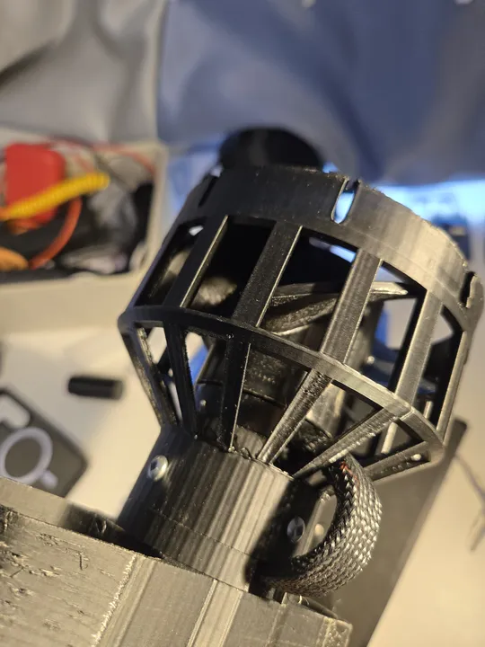
## Building the Pump
The pump uses a high-RPM brushed motor driving a custom impeller inside a modified medical syringe. 3D-printed impellers weren't precise enough at this scale, so I machined one from hard plastic instead. I sealed the chamber with waterproof compounds and set up a gravity feed system to keep it primed.
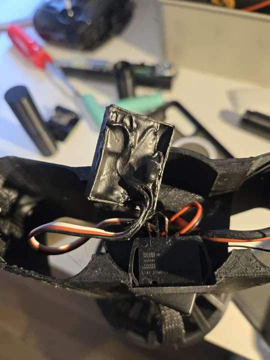
## Electronics & Control
The pump is powered by a small 1S brushed ESC. I connected it to the flight controller's LED pin and remapped it in Betaflight to work like a servo. I also added a button to my transmitter (LiteRadio 2 SE) to trigger the pump without affecting the flight controls.
## What I Learned
- **Construction**: 3D-printed parts with hot glue aren't durable enough for the stress, vibration, and environmental exposure (water, humidity, temperature) of flight. A part detached during a crash, so I need to use epoxy or screws for assembly next time.
- **Waterproofing**: I applied silicone conformal coating to the replacement flight controller to prevent shorts if water gets inside.
- **Tubing**: The first tubes were too stiff and kinked easily. I need to use flexible silicone tubing next time and probably switch to an active priming pump so it doesn't rely on gravity.
---
### Solos HUD: Reverse Engineering & Redesign
Date: 2026-03-22 (Age: 17)
Tier: 1
Category: HARDWARE & SOFTWARE
Description: Reverse engineering Solos smart glasses to build custom apps, followed by a complete hardware redesign and custom 3D-printed housing for enhanced portability and battery life.
GitHub: https://github.com/StudentBroken/solos-hud
[CONTENT]
# Solos HUD Redesign
## Project Overview
I reverse-engineered and physically redesigned the Solos HUD to make it smaller and lighter while keeping it functional. The work involved analyzing how it communicates, taking it apart, modifying the circuit boards, and redesigning the housing from scratch.
## Reverse Engineering
I started by figuring out how the Solos HUD talks to its original app. I analyzed the Android app code and used Bluetooth sniffing to find the exact message format for the display.
*I wrote a custom app to send real-time speed and battery data to the HUD.*
Once I knew how the display worked, I wrote my own software. My custom app reads live speed and power details from my electric skateboard and sends them to the glasses.
## Hardware Modification
I wanted the HUD to fit on regular glasses, so I took it completely apart. I extracted the main circuit board and the glass prism from the original bulky housing.
To make it even smaller, I had to cut the flat cable that connected the two sides. I used a microscope and tiny cutters to do this safely, then sealed everything with UV resin.
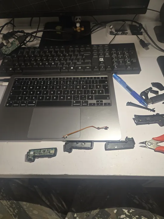
*Fitting the extracted electronics into the new, compact 3D-printed case.*
Cutting the cable disconnected the original battery, thermistor, and charging circuit, so I had to build a completely new power system.
## Tradeoffs
I made several changes to hit my weight and size targets. The final weight dropped from 65g to 53g.
- **Battery Swap**: The original 160mAh cell was old and swollen. I replaced it with a salvaged 380mAh lithium cell from scrap hardware, almost tripling the battery life. Since I cut the charging circuit, I added a standalone USB-C charge module with its own protection circuitry.
- **No Speakers**: I removed the speaker to save space and weight. Audio now comes through external earbuds or a speaker.
- **New Housing**: I designed a flat PETG case that folds up and mounts on any standard glasses frame from AliExpress.
## Bill of Materials
- **Solos HUD (Donor Unit)**: $25 CAD
- **Custom PETG Housing**: ~$3 CAD
- **Eyewear Frames (AliExpress)**: $5 CAD
- **USB-C Charge Module**: $1 CAD
- **Battery (380mAh, salvaged)**: Free
**Total**: ~$34 CAD
## Post-Mortem
The redesigned HUD proves you can take apart consumer electronics and rebuild them into something much smaller. The custom software successfully reads skateboard telemetry and displays it on the HUD in real time, giving a high-resolution speed monitor at a fraction of the original weight and cost.
---
## TIER 1: THE SPOTLIGHT
Production-grade engineering and flagship systems.
### V Plotter: V-Bot
Date: 2026-02-15 (Age: 16)
Tier: 1
Category: HARDWARE & SOFTWARE
Description: A portable, dual-stepper V Plotter capable of drawing on large boards, featuring a web interface and modular crab-inspired gondola.
GitHub: https://github.com/StudentBroken/v-bot
[CONTENT]
# V-Plotter: Drawing Robot with Suspended Carriage
## Technical Objective
Built a V-plotter that draws by hanging a pen carriage from two stepper motors on strings. The motors adjust string lengths to move the pen across a surface based on inverse kinematics calculations.
## Development Timeline
I built this over a few days using borrowed time between school and other projects.
- **Design**: I modeled the frame and carriage during classes.
- **Kinematics**: I worked out the math for the inverse kinematics by hand.
- **Build**: I assembled everything and integrated the code in a single 9-hour session after school.
## Hardware Integration
The system runs on 12V from a USB-C Power Delivery supply (2A maximum).
- **Power Rails**: The 12V powers the stepper drivers directly. A 5V buck converter steps it down for the logic board and servo. The ESP32 uses its internal 3.3V regulator.
- **Main Controller**: ESP32-C3 running a web server for wireless drawing commands and status monitoring.
- **Motors**: Two NEMA 17 steppers suspended from the frame using high-tensile string.
- **Pen Control**: A small servo motor raises and lowers the pen (Z-axis).
- **Cooling**: A small fan blows over the stepper drivers to prevent overheating.
## Inverse Kinematics
The math for this robot was the hardest part. I had to write a custom engine that calculates exactly how long each string needs to be to reach a specific point on the whiteboard.
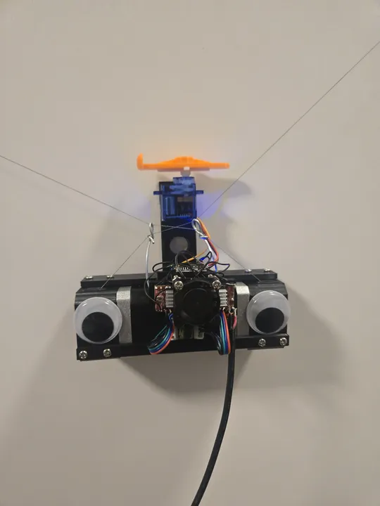
*The robot hanging on a whiteboard. It uses two strings to move the pen.*
Instead of simple X and Y coordinates, the robot thinks in string lengths. I programmed it to "home" itself by pulling both strings all the way in, giving it a known starting point before it begins to draw.
## Bill of Materials
I tried to make this as cheap as possible by using common parts.
- **Motion Kit**: $20.00
- **Brain (ESP32-C3)**: $1.00
- **Power Parts**: $2.50
- **Servo Motor**: $2.00
- **3D Printed Frame**: $5.00
**Total Cost**: ~$30.50
## Post-Mortem
One big failure happened during testing: the cheap motor drivers I bought couldn't handle the power needed to lift the pen. They overheated and literally burned out.
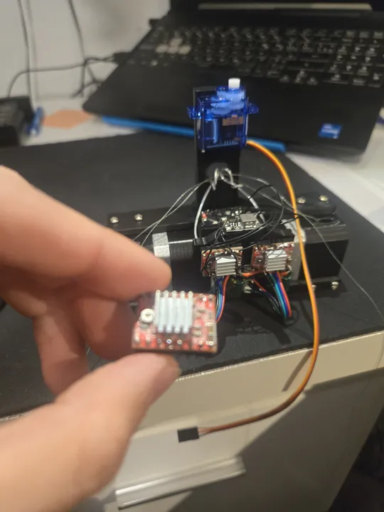
*One of the motor drivers that failed during testing. Next time, I'll use higher-quality parts.*
---
### MBS — Student Grade Tracker
Date: 2025-11-15 (Age: 16)
Tier: 1
Category: SOFTWARE
Description: A collaborative grade tracking platform for Quebec students, developed over 3 months until February 2026. It remains under constant maintenance for ticket and database supervision to this day.
GitHub: https://github.com/StudentBroken/studentbroken.github.io
External Links: Live Site (https://studentbroken.github.io)
[CONTENT]
# MBS — Student Grade Tracker
MBS (Moyenne, Bilan, Stratégie) is a web app for Quebec secondary school students to track, analyze, and rank their grades. The tool has reached 130 active users, representing nearly 50% of the entire Secondary 5 grade level. It was my first project with a real collaborator — Howard — and the first time either of us used GitHub beyond reading code.
Working with someone at a different pace taught me how to manage a project. My collaborator Howard connected the Google Sheets backend and the projection tool. I built the rest: the data formatter, the grade calculator that handles complex weights, the leaderboard, and the user interface.
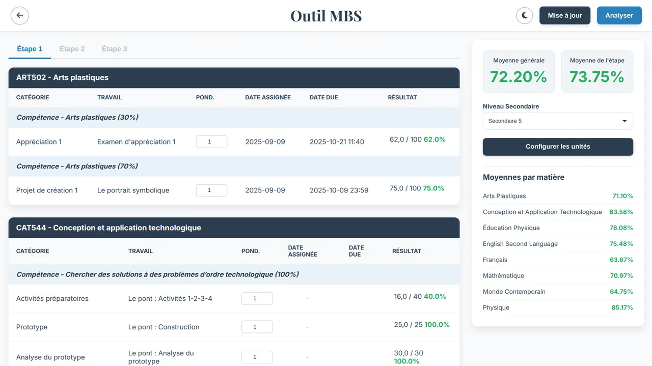
*The main page where students can paste their data from the school portal.*
## Data Ingestion
Students paste raw portal output into the data page. The formatter I wrote normalizes every grading format the Quebec system uses — letter grades (A+, B−), percentages, decimals, fractions — to a 0–100 scale before any calculation runs. Grades are then weighted by assessment type and term across Étapes 1–3 for both Secondaire 4 and 5.
Each parsed snapshot is timestamped and written to `localStorage`, so the dashboard tracks grade changes over time without requiring a login or a persistent server session.
## Average Calculator
The weighted average engine accounts for competency weights within each subject and term weights across the year. It mirrors the actual Quebec grading model rather than treating all grades equally — which is the main reason the numbers it produces match the official portal output.
## Leaderboard & Rankings
Students who opt in share their `mbsData` object. The leaderboard filters to anyone with a global average ≥ 70 and computes rank and percentile:
```
percentile = (total − rank + 1) / total × 100
```
Rankings can be sorted by overall average or by subject. Color coding flags the top 10% and bottom 50% at a glance.
## Grade Projections
Howard built the projection tool: given current grades and remaining assessments, it models the final average needed on each upcoming evaluation to hit a target. It runs on the same weighted calculation engine.
## The Result
The tool is popular because it's fast and private. It processes all data locally in your browser so no one else sees your grades unless you choose to join the leaderboard. This project was a huge step in learning how to handle real user data and complex scoring systems.

*The statistics page shows your performance trends across different subjects.*
---
### Electric Bike (v5)
Date: 2025-10-14 (Age: 16)
Tier: 1
Category: HARDWARE | Series: Electric Bike
Description: A 72V 20S6P rebuild from recycled cells with a dedicated Daly BMS and a real charger — ending the series/parallel charging hack. The build where internal resistance finally clicked as the real measure of cell health.
[CONTENT]
# Electric Bike (v5)
For this version, I decided to fix the "dangerous" charging system once and for all. I moved to a high-voltage 72V system (20S) and bought a professional **Daly BMS** and a real charger. No more plugging and unplugging wires just to charge the bike.
## Planning the Pack
With 120 cells to organize, I used **TinkerCAD** to plan the layout. It allowed me to color-code the groups and make sure every cell fit perfectly inside the frame.
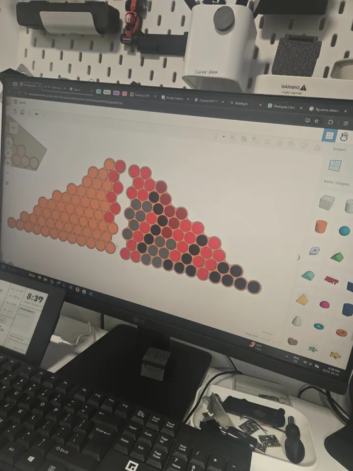
*I used different colors for each group of cells to avoid mistakes during assembly.*
## Nickel Strip Layout & Current Density
This was the second time I used CAD to plan nickel strip paths, and the first time I explicitly calculated current density. Previous builds used nickel strips chosen by feel — wide enough to not obviously fail. Here I worked out the cross-section required to carry the expected peak current without the strips acting as fuses.
The two 10S6P halves were connected to each other using 12AWG silicone wire rather than a long run of nickel strip. Long nickel strip inter-pack connections have higher resistance and are mechanically fragile; 12AWG wire is lower resistance, rated for the current, and flexible.
*Inter-pack connections in 12AWG silicone wire — lower resistance and mechanically robust.*
## Thermal Management
Previous builds wrapped the pack in foam. Foam is an insulator — it traps heat generated by the cells during discharge. v5 uses black tape only, no foam. The cells can dissipate heat directly through the wrap into the air.
## BMS & Charging: Ending the Hack
The v4 series/parallel charging workaround existed because the charger could only handle 6S. v5 runs at 20S — 72V nominal, 84V peak — which a 6S charger cannot touch regardless of topology hacks.
I bought a 40A passive Daly BMS rated for 72V and a matching 2A 72V charger. The BMS handles both charge cutoff and over-current protection properly. The bypass discharge connector is finally gone — the Daly's 40A continuous rating is sufficient for the hub motor's draw without bypassing protection.
Balance leads on a 72V pack are live at potentially lethal voltage across the full string. I wore gloves rated for the work but thin enough to retain tactile feedback for soldering the fine-pitch balance wires.
## Lessons Learned
This was the build where I finally understood **Internal Resistance (IR)**. I realized that a battery's health isn't just about how much energy it can hold, but how easily it can give that energy out. If a cell has high IR, it gets hot and loses power.
I also learned that "amateur" habits like using duct tape were bad practice. I switched to **Kapton tape**, which is the industry standard because it's heat-resistant and doesn't leave a sticky mess.
## Bill of Materials
| Component | Cost |
|---|---|
| 40A 72V Daly BMS | ~$45.00 CAD |
| 72V 2A charger | ~$35.00 CAD |
| Nickel strips + 12AWG wire | ~$20.00 CAD |
| Black tape + misc hardware | ~$10.00 CAD |
| Cells (recycled from v4) | — |
| Hub motor + VESC (carried from v4) | — |
| **Total new spend** | **~$110.00 CAD** |
---
### Electric Underwater Scooter (v2)
Date: 2025-07-02 (Age: 16)
Tier: 1
Category: HARDWARE & SOFTWARE | Series: Underwater Scooter
Description: A brushless upgrade to the v1 scooter using a salvaged 5065 skateboard motor, waterproof ESC, and ESP32-C3, achieving double the speed and more than double the power at minimal cost.
[CONTENT]
# Electric Underwater Scooter (v2)
A brushless redesign of the v1 scooter. The goal was straightforward: more speed, more thrust, and a cleaner electrical system — without spending much more than the original build. The result is roughly double the speed and more than double the power, using mostly salvaged parts.
## Why Brushless
The first version used simple motors that weren't very powerful. This new version uses a brushless motor salvaged from an old electric skateboard. It has much more torque and power, making the scooter twice as fast.
*I used a 5065 motor from a skateboard and a waterproof speed controller (ESC).*
One lesson I learned: drone parts don't work well underwater. Drones need high speed, but underwater propellers need high torque. I had to find an ESC specifically rated for water use.
## Electronics & Potting
The brain of the scooter is an ESP32-C3. It measures the battery voltage and changes the color of an LED to show how much power is left (green for full, red for empty). You can also double-click the main button to switch between low, medium, and high power modes.
*The circuit board is covered in liquid electrical tape to keep it 100% waterproof.*
Because the board is permanently sealed, I had to write special software that lets me update the code wirelessly. If I didn't have this, I would have to break the seal every time I wanted to change something.
Potting with liquid electrical tape seals the board against water without the weight of a plastic case, bringing the cost down to about $5 for materials.
## Firmware Logic
I used AI to build the boilerplate code, focusing my time on the actual control state machine and safety interlocks.
I wrote a custom debounce routine to filter underwater switch noise, and hand-audited the generated code to catch any logic errors that could cause a runaway motor.
## Mechanical Design
The chassis is PLA, designed in CAD and printed on an Ender 3. Getting everything to fit took many revisions — the brushless motor is physically larger than the brushed units in v1, and the waterproof ESC adds volume that had to be routed carefully. The final design is compact and holds together well.
Plastic cost for the chassis was around $10 in filament across all iterations.
## Bill of Materials
- **Motor (Leafboard 5065 Brushless Outrunner)**: Free (salvaged)
- **Speed Controller (60A Waterproof ESC)**: $25.00
- **Controller Board (ESP32-C3 Super Mini + RGB LED)**: $4.00
- **Chassis (3D Printed PLA)**: $10.00
- **Battery (2x 3S 21700 Li-Ion)**: $15.00
- **Potting (Liquid Electrical Tape)**: $5.00
**Total Out-of-Pocket Cost**: ~$59.00
## Lessons Learned
- **Drone ESCs fail underwater.** The torque characteristics are wrong for propeller loads at low RPM. Use an ESC rated for the application, not repurposed quadcopter hardware.
- **KV is poorly documented on cheap motors.** If the KV is unlisted, expect to test empirically rather than calculate gear ratios or prop pitch in advance.
- **Potting works.** Liquid electrical tape is inexpensive, easy to apply, and effective at sealing low-profile boards. It is now the default approach for any electronics near water.
---
### Smart Ebike Charger
Date: 2025-06-18 (Age: 16)
Tier: 1
Category: HARDWARE & SOFTWARE
Description: ESP32-based smart charger for a custom 6S ebike battery pack, designed to safely use a LiHV charger on standard LiPo cells by cutting off at a timed voltage threshold that accounts for IR drop. WiFi-enabled with live web dashboard and OLED display.
[CONTENT]
# LiHV Cutoff Controller
The ebike runs on a custom 12S pack built from two 6S LiPo packs in series. The only charger available was the 6S LiHV unit that originally shipped with a Leafboard Gen 1 electric skateboard — the same board whose motor was later salvaged for the ebike v1 and the underwater scooter v1. That charger is designed to push cells to 4.35V each (26.1V for a 6S pack) rather than the standard LiPo maximum of 4.2V per cell (25.2V). Running a LiHV charger on standard LiPo cells risks overcharge, puffing, and eventual cell failure.
The solution was a relay-based cutoff controller that intercepts the charger output and disconnects it at the right moment.
## The Cutoff Design
I built a simple relay-cutoff for a LiHV charger using an ESP32. I added a timer to make sure it doesn't shut off too early when the voltage drops under load. For a version 2, I would build a proper charging circuit, as mechanical relays aren't the best for cutting high power.
## Hardware
The system uses a small ESP32-C3 computer and a relay to handle the power. I added an OLED screen so I can see the charging progress and the device's IP address at a glance.
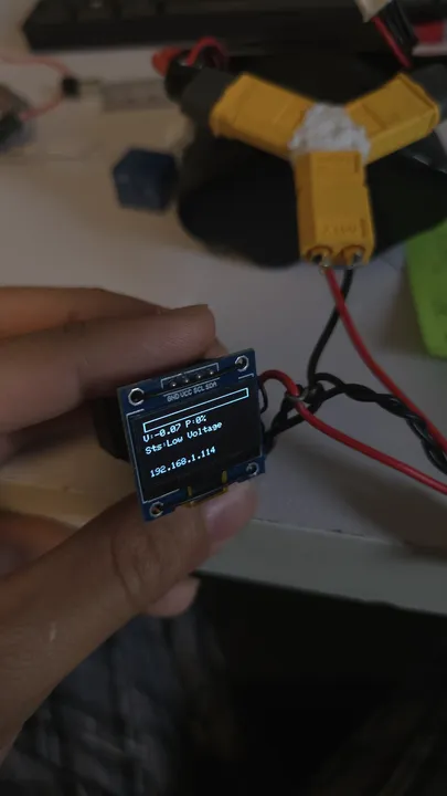
*The OLED screen shows the battery voltage and a progress bar.*
## Web Interface
When you plug it in, the charger connects to your WiFi. You can open a dashboard on your phone or laptop to see exactly what's happening. I added buttons to manually turn the charger on or off, and a settings page to change things like the cutoff voltage without needing to rewrite the code.
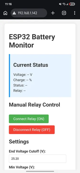
*The web interface lets you monitor and control the charger from any device.*
## Bill of Materials
AliExpress pricing; ESP32-C3 was $1.
| Component | Unit Cost |
|---|---|
| ESP32-C3 Super Mini | $1.00 |
| SSD1306 OLED display | $1.10 |
| L7805CV 5V LDO regulator | $0.45 |
| 5V relay module | $1.00 |
| NPN transistor | $0.05 |
| Resistors (3 total) | $0.02 |
| Electrolytic capacitors (2 total) | $1.00 |
| Wire (22AWG) | $0.50 |
| XT60 connectors | $0.75 |
| **Total** | **~$5.00** |
## Control Logic
The firmware runs four safety checks:
1. **No-load detection**: open circuit detection.
2. **Under-voltage protection**: prevents over-discharged cells from charging.
3. **Charge complete**: prevents relay oscillation.
4. **Normal charging**: cuts off the relay when voltage and time thresholds are met.
---
### Electric Bike (v4)
Date: 2025-06-02 (Age: 16)
Tier: 1
Category: HARDWARE | Series: Electric Bike
Description: A 2000W hub motor build on 12S, constructed from two 6S packs wired in series for riding and in parallel for charging. A short circuit from a wiring mistake destroyed both BMS units — and led to conformal coating and a 'remove before flight' tag.
[CONTENT]
# Electric Bike (v4)
## Building the Wheel
For this version, I moved to a "hub motor" system. This means the motor is actually part of the rear wheel itself. Since I bought just the motor, I had to learn how to "lace" it into a rim using metal spokes.
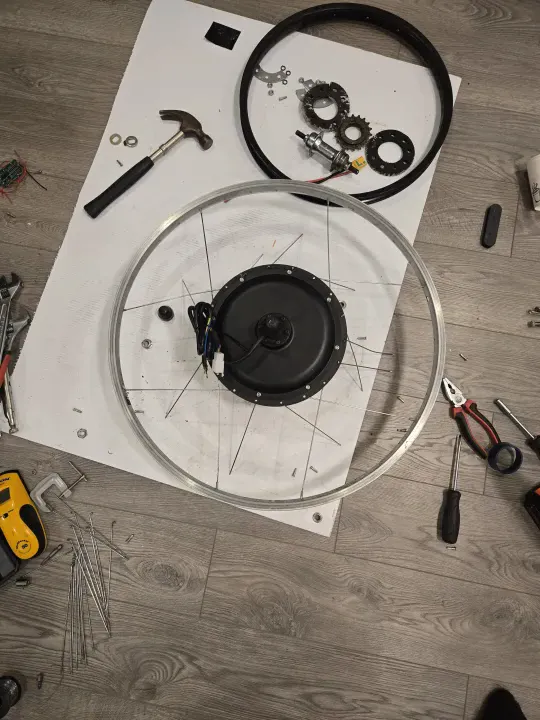
*Learning how to lace a wheel. It took a full day and several tries to get the tension right.*
It was a slow, frustrating process, but eventually, I had a working 2000W wheel that could push the bike much faster.
## The Dual-Battery "Hack"
I built two separate 22V (6S) battery packs. To ride, I plugged them together in "series" to get 44V (12S). To charge, I unplugged them and plugged them together in "parallel" so I could use a cheaper 22V charger.

*Notice the "Remove Before Flight" tag—I added that after a wiring mistake almost caused a fire during charging.*
One day, I accidentally plugged the batteries in the wrong way and saw actual sparks. I destroyed two safety boards (BMS) before I learned to be more careful.
This required a manual switching step between modes. Each pack had its own $6 BMS for charge protection. For discharge I used the bypass trick from v2: a second output connector that goes around the BMS entirely so the full current hits the VESC without restriction.
I used a Sharpie on green painter's tape to diagram the cell connections before spot welding — a system that worked well for keeping track of the series/parallel topology during the weld sequence.
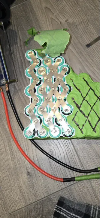
*Sharpie on painter's tape — wiring diagram drawn directly on the pack before welding.*
## The Short Circuit
I plugged in the parallel charge connector while the series key was still connected. This created a dead short across both BMS units simultaneously — enough current to destroy them both instantly. Two $6 BMS units, both gone in one mistake.
The root cause is a logic problem: the series and parallel states are mutually exclusive, but there was no physical enforcement of that constraint. Both connectors were accessible at the same time. For v5 this would need an interlock — either mechanical keying or a relay that physically disconnects series before parallel charging is possible.
After replacing the BMS units, I conformal coated both boards for water resistance and added a "remove before flight" tag on the series key connector so I could not miss it before plugging in the charger.
## 3D Printed Battery Mounts
I printed tolerance-test iterations of the battery mount before committing to the final part. The mount held mechanically but PLA is brittle — it cracked under vibration and impact over time. This was the build that confirmed for me that PLA is the wrong material for any structural frame component on a vehicle. PETG or ASA for anything that takes load or vibration; PLA only for static brackets.
## VESC Enclosure
The VESC started in a soft bag strapped to the frame. I later designed and printed a cover with airflow passages to keep it cooler under sustained load.
## Conclusion
This bike was very fast but the charging system was too complicated. Every time I wanted to charge, I had to play with a bunch of wires. It was a great learning experience, but it proved that I needed a better way to handle high-voltage batteries.
## Bill of Materials
| Component | Cost |
|---|---|
| 2000W Hub Motor | ~$300.00 CAD |
| 26-inch rim (for lacing) | ~$30.00 CAD |
| 18650 cells | ~$50.00 CAD |
| 2× BMS (destroyed + replaced) | ~$24.00 CAD |
| VESC (carried from v3) | — |
| 3D print filament + misc | ~$15.00 CAD |
| **Total new spend** | **~$419.00 CAD** |
---
### Head Tracking DJI O3 Air Unit
Date: 2024-10-18 (Age: 15)
Tier: 1
Category: HARDWARE & SOFTWARE
Description: A 2-axis head tracking system for the DJI Goggles 3 and O3 air unit using an MPU module and ESP32 C3 Superminis.
[CONTENT]
# Head Tracking DJI O3 Air Unit
A 2-axis head-tracking gimbal system built for the DJI Goggles 3 and O3 Air Unit. Two ESP32-C3s communicate over ESP-NOW — one on the goggles reading head orientation, one on the drone driving the servos.
The mechanical design was sketched out during a math exam. The teacher was not pleased.
## Hardware
The gimbal is custom-designed and 3D printed. It uses two micro-servos to move the camera up, down, left, and right. It can run on almost any drone battery (2S to 6S) thanks to a built-in power regulator.
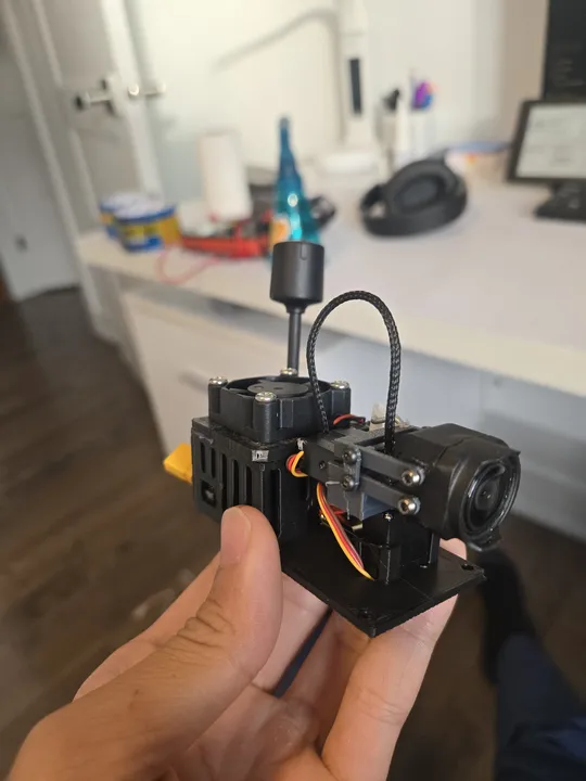
*The finished gimbal with the DJI O3 camera mounted.*
- **On the Goggles**: An ESP32 and a gyro sensor to track your head.
- **On the Drone**: An ESP32 and two servos to move the camera.
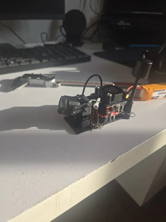
*Testing the servos and electronics on the workbench before mounting.*
## Bill of Materials
The DJI O3 Air Unit is not included — it's shared with the FPV drone builds.
| Component | Cost |
|---|---|
| ESP32-C3 Super Mini × 2 | $2.00 |
| MPU6050 gyro/accelerometer module | $3.00 |
| Micro-servos × 2 (pan + tilt) | $5.00 |
| Switching buck converter | $1.00 |
| Cooling fan (small) | $2.00 |
| 3D printed parts (PLA) | $3.00 |
| Misc (wire, connectors, hardware) | $1.00 |
| **Total** | **$17.00** |
## Transmitter Firmware
The goggles-side ESP32 uses the MPU6050's onboard motion processor to compute yaw and pitch, avoiding drift from integrating raw gyro data. On boot it collects 200 motion samples at rest and computes offsets, so the gimbal centers itself regardless of how the goggles are sitting when powered on.
Only yaw and pitch are transmitted — roll is discarded since the gimbal has no roll axis. Each packet carries the two angles, a sequence number, and a checksum. The receiver uses both to reject duplicate, out-of-order, and corrupted packets.
## Receiver Firmware
The drone-side ESP32 receives packets, validates the checksum and sequence number, then maps the angles to servo pulse widths. Yaw maps to ±90° pan, pitch maps to ±45° tilt. A 0.5° input deadzone prevents the servos from drifting around center when the head is still.
Servo movement is smoothed with an exponential filter to eliminate jerkiness from discrete angle steps. If no valid packet arrives for 1.5 seconds, the servos return to center automatically, so a lost link doesn't leave the camera pointing at the ground.
The receiver drives the servos directly without going through the flight controller, keeping latency low.
## Gyro Drift & Calibration
The biggest challenge was drift. All gyros naturally "drift" over time, making the camera slowly move even if you keep your head still. To fix this, I used a motion processor that fuses gyro data with an accelerometer. The accelerometer uses gravity as a fixed reference to keep the gimbal centered.
I also added a calibration step that runs every time you power it on. It measures the resting position of your goggles so the camera always starts perfectly centered.
---
### Electric Bike (v3)
Date: 2024-08-01 (Age: 15)
Tier: 1
Category: HARDWARE | Series: Electric Bike
Description: A mid-drive conversion using a 6384 outrunner motor mounted to the frame with hardware-store L-brackets, reaching 45 km/h. Built at 15, this was the first attempt at metal fabrication and proper gearing math — and the build that killed two VESCs.
External Links: VescBLEBridge (GitHub) (https://github.com/A-Emile/VescBLEBridge)
[CONTENT]
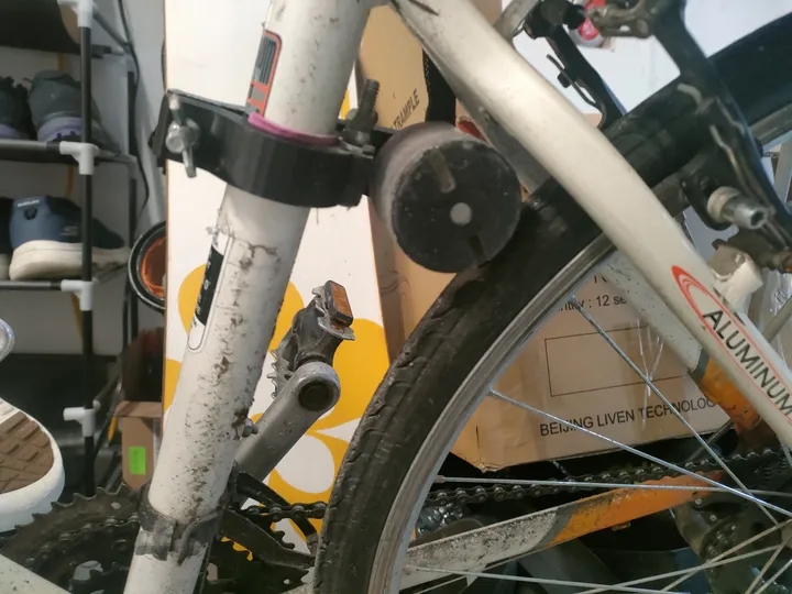
# Electric Bike (v3)
By age 15, I wanted the bike to have more torque. Instead of the motor spinning the tire directly, I built a "mid-drive" system that used a chain and sprocket. This meant the motor could help the bike climb hills much better.
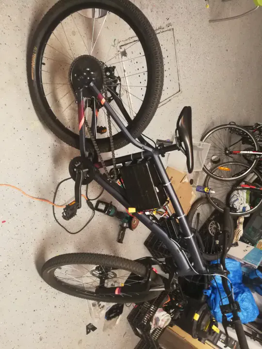
*The finished v3 model. You can see the large motor and the chain drive system.*
## Drivetrain & Gearing
I removed the pedal chain entirely and mounted a 10-tooth sprocket on the 6384 outrunner motor, driving the stock 33-tooth rear wheel sprocket. That gives a 3.3:1 reduction. At 120KV and 6S (roughly 22V), the motor spins at around 2640 RPM at no load, which drops to a usable wheel speed around 45 km/h once the reduction is applied.
The gears were cheap Chinese chainrings sourced online. They worked, but the chain tension was never stable because of the mount.
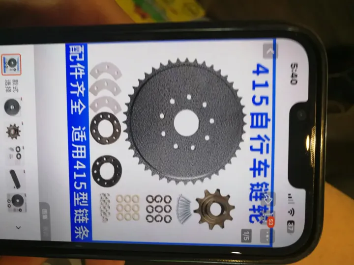
*10T motor sprocket to 33T rear — 3.3:1 reduction.*
## Motor Mount
The motor was attached to the frame using the water bottle cage mounts as anchor points, plus hardware store L-brackets. To clamp the L-brackets securely to the frame tubes, I cut a groove in each bracket and threaded a metal screw tie through it, then cinched it around the tube. It held, but it was not rigid under dynamic torque — the brackets still deformed over time.
For the first time I also used rivnuts. I had no proper rivnut tool, so I fabricated a contraption from whatever hardware I had at hand to pull the mandrel and set them. It worked well enough to be a permanent fixture. The rivnuts gave me threaded inserts in the frame without welding, which was the right call given the tools available.
I also modeled up a 3D-printed PLA bracket for the battery tray from the frame fitment reference photo, and mounted the VESC at the front of the frame.
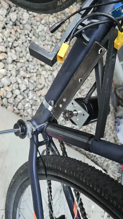
*Motor mount, PLA battery tray, and VESC visible. Functional, barely.*
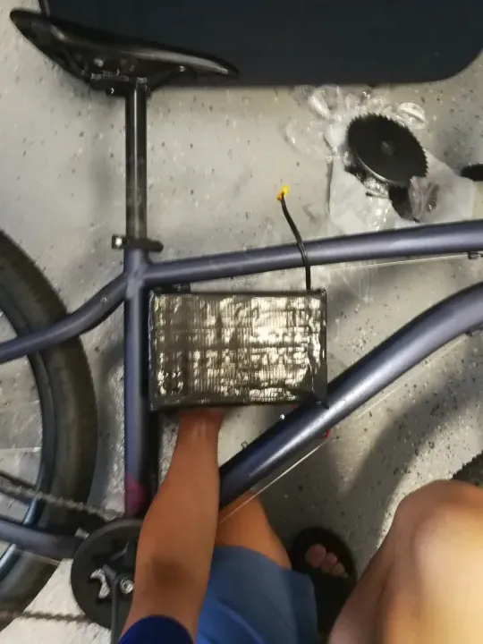
*Photo used as reference geometry for the 3D printed bracket.*
## My First Spot Welder
I also finally stopped soldering directly to battery cells. I bought a cheap battery spot welder from AliExpress. This uses high-current pulses to fuse a thin nickel strip to the cell without heating up the entire battery.
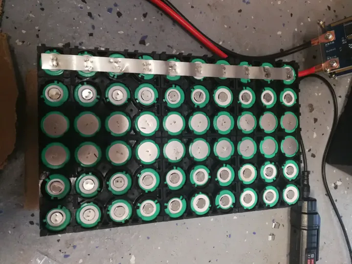
*Learning how to spot weld. It's much safer and more reliable than soldering.*
It took some practice to get it right, but this was a huge step toward building professional-quality battery packs.
*Pack interior — foam padding and duct tape, consistent with the v1/v2 build standard.*
## Dashboard
Before adding the BLE bridge, I built a local dashboard: a 0.91-inch OLED wired to an ESP32, displaying speed, battery voltage, and SOC in real time. I knew voltage alone tells you the state of charge on a lithium cell when the pack is at rest — voltage under load is a different story, but for a rough fuel gauge it was sufficient.
The OLED was the reason the first VESC died. While wiring the ESP32 to the VESC UART connector, I accidentally shorted a data pin to ground. That was enough to kill the BEC. Not a component quality failure — a wiring mistake. It was only after I replaced the VESC and looked more carefully at what happened that I understood the root cause.
## BLE Telemetry
For the first time, I added real-time telemetry. I flashed an open-source project — [VescBLEBridge](https://github.com/A-Emile/VescBLEBridge) — to an ESP32, which bridges the VESC UART output to Bluetooth Low Energy. This let me read voltage, speed, and current from my phone while riding. First time using PlatformIO and VSCode for an ESP32 project (I had used PlatformIO before at 13 for flashing Klipper to an Ender 3, but this was different — compiling and uploading actual firmware logic, not just a config).
## VESC Failures
This build killed two VESCs:
**VESC #1** — same 75100 model, bought cheap. The internal BEC failed. The actual cause was my own fault: while wiring the OLED ESP32 to the VESC UART, I shorted a data pin to ground and killed the BEC. I did not realize this at the time and assumed it was a component failure.
**VESC #2** — same result. Different unit, same failure. At this point two identical controllers failed in identical ways on identical hardware, which means the budget 75100 BEC is the weak link, not my wiring or setup.
**VESC #3** (current) — sourced from a more reputable seller at $75. Still has a known defect: the ADC reads voltage approximately 1V higher than actual. Liveable at $75. In all other functions it works correctly. You get what you pay for.
## Bill of Materials
| Component | Cost |
|---|---|
| 6384 Outrunner 120KV | ~$40.00 CAD |
| VESC 75100 ×2 (both failed) | ~$120.00 CAD |
| VESC 75100 (reputable seller) | ~$75.00 CAD |
| Chainring + 10T motor sprocket | ~$20.00 CAD |
| L-brackets + hardware | ~$10.00 CAD |
| 18650 cells (~$1 each) | ~$50.00 CAD |
| ESP32 + misc | ~$10.00 CAD |
| **Total** | **~$325.00 CAD** |
## The Cost of Failure
This build was a hard lesson in power electronics. I managed to burn out two expensive VESCs. The second one failed when I tried to go up a steep hill while the motor was still cold. The sudden spike in current was too much for the controller.
In the end, this version reached 45km/h, but it was often broken. It taught me that building a powerful bike is much harder than just making a fast one.
---
### Electric Bike (v2)
Date: 2023-03-11 (Age: 14)
Tier: 1
Category: HARDWARE | Series: Electric Bike
Description: A VESC-powered upgrade of the v1 friction-drive ebike, reaching 40 km/h on the same dangerous hand-soldered 6S8P pack — now with a BMS bypass and a detachable magnetic joystick throttle.
[CONTENT]
# Electric Bike (v2)
After the first motor controller failed, I bought a **VESC 6.7 Pro**. This was the first time I spent real money on a single part ($120). It made the motor run much smoother and even allowed the bike to charge itself slightly when braking (regenerative braking).
## The BMS Bypass
In the first version, the battery safety board (BMS) kept burning out because I was pulling too much power. To fix this, I rebuilt the battery with two plugs. One plug went through the BMS for safe charging, but the other plug went straight to the motor, bypassing all safety.
*One plug is for charging, the other provides raw power directly to the motor.*
This was a bad idea. It meant there was no protection if something short-circuited. I knew it was risky, but I wanted the bike to be fast. I also saw that the original BMS had actual scorch marks from where it failed.
*The first BMS couldn't handle the current and started to melt.*
## VESC Configuration
First time using a VESC. I set battery max current to 40A, motor current to 40A, and left most other settings at their defaults after reading what each parameter actually did. The VESC handled the motor cleanly and gave regenerative braking — a huge step up from the RC ESC, which just cut power and coasted.
I spent a day on this. By end of day I understood current limits, duty cycle control, ADC input modes, and why RC ESCs fail in this application (they are tuned for propeller loads, not motors that stall, reverse, and experience high inertia).
## Magnetic Throttle
I also redesigned the throttle. I used a small joystick module and hot-glued magnets to the bottom. I then glued magnets to the handlebars so the joystick could snap on and off instantly.
*The magnetic mount made it easy to take the throttle off when I parked the bike.*
## Performance and the McGill Expo Ride
Top speed was around 40 km/h. I had no display or watt meter, so I carried a multimeter in my bag on the rear rack and checked resting cell voltage by hand when I stopped.
I rode to the McGill Engineering Expo that summer — 20 km from the South Shore, crossing the bridge. Got there with the pack sitting at roughly 3.5V per cell — close enough to the 3.0V low-voltage cutoff that I stopped and did not push further. At the expo, I tried asking the engineering department if I could borrow a DC bench supply to charge my pack to exactly 25.2V (4.2V/cell × 6S). Nobody took me seriously. I was 13.
## Bill of Materials
The only new cost on this build was the VESC — everything else carried over from v1.
| Component | Cost |
|---|---|
| VESC 6.7 Pro | ~$120.00 CAD |
| Joystick throttle module | ~$10.00 CAD (salvaged) |
| Magnets + epoxy | ~$5.00 CAD |
| **Total new spend** | **~$135.00 CAD** |
## Post-Mortem
The friction drive was the mechanical weak point. I was constantly re-tensioning the motor against the tire. This was worsened by **PLA Creep**: the main motor holder was 3D printed in PLA and held under constant tension to keep the motor pressed against the wheel. PLA deforms under sustained load over time. I realized this too late, and it served as a permanent lesson to never use plastic for structural, high-tension motor mounts. I upgraded to metal and never went back.
Around the same time, the VESC failed—specifically the internal BEC (Battery Eliminator Circuit). I never found out why it broke. As a 13-year-old with a $10 soldering iron, I tried to fix it myself after being ignored by a micro-soldering guy on Facebook Marketplace. Predictably, trying to do micro-soldering on a high-density PCB with a cheap iron just ruined the traces. The VESC was eventually scrapped.
The battery remained the biggest risk — and looking back, the BMS bypass was a genuinely bad idea that I would not repeat. At the time, my only experience with batteries was LiPo packs with balance leads. With a balanced, fully charged LiPo pack, you can discharge to around 10% without meaningful cell drift — the cells track each other closely when they start in balance. That was my mental model here: if the pack was charged and balanced, I just needed to avoid a dead short and not over-discharge. I did not yet understand that a purpose-built battery pack from salvage cells with hand-soldered copper bus bars and no individual cell monitoring was a fundamentally different risk category. I did not fully internalize why that distinction mattered until around v4-v5.
The wiring made it worse. I bought cheap PVC-insulated wire from a local hardware store. PVC insulation starts to soften and melt around 60–70°C, and at 40A it was clearly running warm. The insulation was visibly deforming on longer rides. Silicone wire handles heat properly; PVC does not. That was a fire risk I did not even know I was carrying.
---
### Electric Bike (v1)
Date: 2023-02-25 (Age: 13)
Tier: 1
Category: HARDWARE | Series: Electric Bike
Description: A friction-drive e-bike built at 13 from marketplace 18650 cells, a salvaged leafboard motor, a cheap RC ESC, and a hand-soldered 6S8P battery pack.
[CONTENT]
# Electric Bike (v1)
I built this bike when I was 13. I didn't have a lot of money, so I used a "friction drive" system. This means the motor sits directly on the tire and spins it using a piece of sandpaper tape.
*Sandpaper tape on the motor provides grip against the rubber tire.*
It wasn't very efficient and the tape wore out quickly, but it was the easiest way to make the bike move without a chain or gears.
## Hand-Soldered Battery
The battery was my first big electronics challenge. I used 48 individual 18650 cells that I bought from the Facebook Marketplace. Since I didn't have a spot welder, I soldered thick copper wires directly to the cells.
*I used thick copper wires from an old extension cord to connect the cells.*
This was a dangerous way to build a battery because the heat from the soldering iron can damage the cells. I wrapped the whole thing in foam and blue duct tape to keep it together.
## Conclusion
The bike worked for a few weeks, reaching about 20km/h. Eventually, the cheap motor controller (ESC) burned out because it wasn't meant to handle the high current needed to start the bike from a stop.
## Throttle
The ESC needed a PWM signal in the standard RC range. A potentiometer outputs analog voltage. I could not find a ready-made adapter, so I wired a cheap pot into an Arduino Nano and wrote a short sketch to read the ADC and output a mapped PWM signal on a servo pin. The Nano ran off the ESC's BEC.
*Arduino Nano reading the pot and outputting PWM — powered from the ESC's built-in 5V BEC*
The throttle body itself was 3D printed, with a small lever sized for one finger.
## What Came Next
After the ESC died, my dad got me a VESC 6.7 Pro. That became v2 — a much more reliable build that I actually rode for a full year and took on longer trips.
The CAD files for the printed parts are probably gone. The machine I was printing on at the time had no remote backup and no Klipper, so nothing was saved. I have not been able to find them.
---
## TIER 2: SIMPLE PROJECTS
Rapid prototyping, R&D, and proof-of-concept builds.
### Heated FPV Battery
Date: 2026-01-30 (Age: 16)
Tier: 2
Category: HARDWARE
Description: An ESP32-C3 powered active heating system to maintain FPV battery temperatures in extreme -30°C winter conditions.
[CONTENT]
# Heated FPV Battery Case
## The Goal
I wanted to keep my FPV batteries warm so I could fly in freezing cold weather (down to -30°C). When LiPo batteries get too cold, they lose capacity and sag under load, so I built a case with a built-in heater to maintain temperature.
## The Electronics
I used two 5V regulators: one for the ESP32-C3 and another to power a nichrome heating wire that outputs 5 watts. I used a thermistor to monitor battery temperature.
## How it Performed
The system performed well. Even at -30°C, the temperature dropped only 0.1°C per minute when not in use. While flying, the heater and battery's own heat kept everything at about 30°C, which is ideal for discharge performance.
## Why it Broke & How to Fix It
I accidentally plugged the battery in backwards while in the field and fried the electronics.
- **Mistake**: I didn't use a polarized connector.
- **Result**: The regulators failed immediately.
- **Next time**: I need to use proper polarized connectors (like XT30 or XT60) and add reverse-polarity protection.
---
### 3-Inch FPV Drone
Date: 2025-10-09 (Age: 16)
Tier: 2
Category: HARDWARE | Series: FPV Drone
Description: 3-inch FPV build on a Baby Ape carbon fiber frame, running the same FC as a Cinelog 20 with a MacGyvered DJI O3 air unit on custom 3D printed standoffs. Built in two hours.
[CONTENT]
# 3-Inch FPV Drone with DJI O3
## The Goal
I wanted to put a high-definition DJI O3 digital system onto a tiny 3-inch drone frame while keeping it under 250g. This required careful placement of components to achieve the best video quality in a tight physical space.
## Custom Adapters
The flight controller didn't fit the DJI O3 unit's mounting holes. I 3D-printed custom standoffs to bridge the gap and maintain proper alignment. This also prevents movement and vibration during high-speed flight.
## The Result
I built the whole thing in under two hours. It flies well and maintains stable video. Having HD video on a 3-inch drone makes it much easier to navigate compared to analog systems, all while staying in a very small package.
---
### 5-Inch FPV Drone
Date: 2025-09-14 (Age: 16)
Tier: 2
Category: HARDWARE | Series: FPV Drone
Description: Full 5-inch FPV freestyle build on a $500 budget including the DJI O3 air unit, with custom 3D printed TPU mounts for the FC and VTX stack.
[CONTENT]
# 5-Inch Freestyle Platform: Vibration Isolation Analysis
## Design Specification
I built a 5-inch racing drone with a focus on getting clean HD video. The main goal was to isolate the video transmitter from vibration.
## Vibration Mitigation
The flight controller and video transmitter (DJI O3) are mounted on custom TPU rubber standoffs. TPU absorbs high-frequency vibrations from the motors and propellers, which keeps the camera image stable and gives the flight controller cleaner sensor data.
## Assembly & Thermal Management
I routed cables carefully and added shielding to keep power clean and prevent interference. Everything is packed tight in the carbon fiber frame.
## Results
Test flights showed the vibration isolation works—much cleaner video compared to a rigid mount. The O3 system delivers the video quality I need for freestyle flying and freestyle maneuvers.
---
### FPV Gel Blaster Drone
Date: 2025-05-10 (Age: 16)
Tier: 2
Category: HARDWARE
Description: 6-inch analog FPV drone rigged to carry and fire a gel blaster, combining FPV freestyle hardware with a combat payload.
[CONTENT]
# FPV Drone with Gel Blaster
## The Goal
I wanted to mount a gel blaster onto a 6-inch FPV drone and fire it remotely. The goal was to use the drone's camera to aim and shoot while flying.
## How I Built It
I mounted a gel blaster to the drone frame and used a MOSFET circuit to trigger the blaster from the remote control. I used analog video for its low latency, which is critical for aiming while moving.
- **Drone**: 6-inch freestyle configuration.
- **Camera**: Analog FPV system.
- **Blaster**: Gel projectile gun integrated into the frame, remote-triggered.
## How it Flies
Adding the blaster increased the weight and shifted the center of gravity. I retuned the flight controller PID values to compensate for the extra mass and vibration from the firing mechanism. The drone flies well and the system works reliably.
---
### April Fools ESP32 Prank Devices
Date: 2025-04-01 (Age: 16)
Tier: 2
Category: HARDWARE & SOFTWARE
Description: Fleet of ESP32 prank devices deployed on April Fools using ESPNow — the first time deep sleep was used to extend battery life. Came with 3D printed fake AirPods as decoy props.
[CONTENT]
# Remote-Controlled Prank Devices
## The Goal
I wanted to build a set of small, hidden devices that could make sounds on command. The main goal was to test how long I could keep an ESP32 running on a tiny battery using "deep sleep" mode.
## How They Communicate
I used several ESP32 boards talking to each other through "ESP-NOW." This lets them coordinate without needing a WiFi router, making them easier to hide. I 3D-printed custom cases that look like normal electronics so they wouldn't be noticed.
## Saving Battery
This was my first time really getting deep-sleep to work well. I set the devices to wake up only when needed, which let them run for a full 24 hours on a very small battery. I chose ESP-NOW because it's much faster and more efficient than regular WiFi.
- **Deep Sleep**: Nodes wake up only at certain times to save power.
- **Efficiency**: The timer was set to last 24 hours on a tiny battery.
- **Protocol**: ESP-NOW was chosen because it connects almost instantly.
## What I Learned
The project worked well. I successfully made battery-powered devices that stayed connected over 24 hours on minimal power. The power-saving code I developed here became the foundation for my later projects, like the ESP Erasers.
---
### Smart Glasses for the Blind
Date: 2025-03-31 (Age: 16)
Tier: 2
Category: HARDWARE
Description: Glasses fitted with an ultrasonic sensor and speaker that beep to warn visually impaired people of nearby obstacles.
[CONTENT]
# Ultrasonic Smart Glasses
## The Goal
I wanted to build a pair of glasses that helps you "see" obstacles using sound. The goal was to use an ultrasonic sensor to detect how far away things are and give real-time feedback.
## The Parts
I used an HC-SR04 ultrasonic sensor mounted on regular glasses frames. A small computer reads the sensor data and calculates the distance to the nearest object.
- **Sensor**: Ultrasonic distance sensor.
- **Speaker**: Small built-in audio driver.
- **How it works**: The glasses beep faster as you get closer to something, making it easy to tell where obstacles are.
## Design
I kept the electronics small so the glasses stay comfortable to wear. I also routed the wiring along the arms of the frame to avoid snagging or breaking during use.
## What I Learned
The beeping system worked well for navigating around things. The main issue was that it only looks straight ahead — it doesn't see what's to the sides. To fix this in a future version, I'd need to add more sensors for a wider field of view.
---
### Static Electricity Generator
Date: 2025-03-19 (Age: 16)
Tier: 2
Category: HARDWARE
Description: High-voltage static electricity generator using a voltage multiplier and AC HV circuit, repurposed as a wearable negative ion generator with a ground plane touching the floor.
[CONTENT]
# Static Electricity Generator
## The Goal
I wanted to build a high-voltage generator that can create sparks and ionize the air. I used a voltage multiplier circuit (Cockcroft-Walton) to turn low voltage into thousands of volts.
## The Circuit
I used a high-voltage multiplier to boost the power. This setup successfully creates sparks and ionizes the air.
- **Circuit**: High-voltage multiplier stack.
- **Output**: High voltage (kV range), very low current.
- **Insulation**: Heavy insulation to stop the spark from jumping where it shouldn't.
## Testing it as a Wearable
I modified the setup to test it as a wearable ion generator.
- **How it works**: I became the high-voltage electrode while standing on a conductive mat connected to ground.
- **Results**: It creates negative ions that neutralize dust in the air.
## Safety & Results
Because of the high voltage, I had to be careful with safety:
- **Separation**: I kept all high-voltage parts separated or insulated.
- **Current limiting**: I added large resistors to keep the current at a safe level.
- **Testing**: I confirmed it was working when my hair started standing up and I could smell the ozone.
---
### Custom RC Flying Wing
Date: 2025-02-24 (Age: 15)
Tier: 2
Category: HARDWARE & SOFTWARE
Description: Fully custom RC flying wing with a scratch-built controller board translating ELRS CRSF signals to SBUS for the servos via an ESP32. Never flew — lives in the project drawer waiting for its moment.
[CONTENT]
# RC Flying Wing: Custom Electronics
## The Goal
I wanted to build a custom control board for a small flying wing. The main goal was to make a single circuit board that could translate different radio signals (CRSF to SBUS) and handle all the electronics at once.
## How it Works
I used an ESP32 to bridge the high-speed CRSF signal from my receiver to the older SBUS protocol that the flight controller uses. I also integrated the servos, video transmitter, and camera into one custom PCB to keep the plane light and balanced.
- **Radio**: ELRS (ExpressLRS) via CRSF.
- **Brain**: ESP32 (custom CRSF to SBUS translation).
- **Servos**: Dual high-torque 2g micro-servos.
## Summary & Status
Everything worked on the bench—signal translation was clean and the custom board performed as expected. The plane is ready to fly, but I've put it on hold to focus on faster drone projects. It proved I could build custom flight electronics from scratch.
---
### Air Quality Sensor
Date: 2025-01-21 (Age: 15)
Tier: 2
Category: HARDWARE & SOFTWARE
Description: ESP32-based sensor logging PM2.5, VOCs, temperature, and humidity, with an OLED readout and an Adafruit MQTT dashboard. Enclosure uses a cheap IKEA part as the structural base.
[CONTENT]
# Air Quality Sensor
## Scope
Built an air quality monitor to track PM2.5 particles, volatile organic compounds (VOCs), and temperature and humidity.
## Hardware Integration
The core is an ESP32-C3 microcontroller. I paired it with a gas sensor for VOC and CO2 readings, and a laser-based particle sensor for PM2.5. The sensors are mounted in a hybrid enclosure—a commercial frame with a custom 3D-printed cover.
## Data Logging
The firmware polls sensors on a schedule and pushes the data to an Adafruit MQTT broker. Telemetry is viewable locally on a small OLED screen or remotely on a cloud dashboard.
## Results
I can clearly track patterns: PM2.5 heavily spikes during 3D printing, cooking, and when using spray products. The sensor is sensitive enough to catch these changes reliably.
---
### BLE Macropad — v2
Date: 2025-01-10 (Age: 15)
Tier: 2
Category: HARDWARE & SOFTWARE | Series: BLE Macropad
Description: Second iteration of the BLE macropad, adding an OLED display and a potentiometer knob for volume or scroll control.
[CONTENT]
# Macropad v2: BLE Keyboard with Display and Knob
## Design Evolution
The second iteration adds a display and analog knob to the v1 design. The goal was to expand the input surface while keeping the wireless architecture unchanged.
## Hardware Specification
I kept the same ESP32-S3 but added an I2C OLED display and a potentiometer.
- **Display**: 0.96" OLED (I2C) showing the current layer and key bindings.
- **Analog Control**: Potentiometer knob for volume, scrolling, or other variable parameters. The firmware debounces the input in software.
- **Main processor**: ESP32-S3 with BLE HID stack.
## System Integration
I redesigned the case to fit the potentiometer and display. The web configuration tool from v1 was reused without changes, so existing keymaps load automatically on startup.
## Post-Mortem
The knob makes it much easier to control volume or scroll through timelines without reaching for another device. The display gives instant feedback about which layer is active and what the keys do. The macropad is now my daily driver for text editing and media controls.
---
### BLE Macropad — v1
Date: 2025-01-06 (Age: 15)
Tier: 2
Category: HARDWARE & SOFTWARE | Series: BLE Macropad
Description: Wireless BLE macropad built around an ESP32 S3, with a web interface for remapping keys. Used daily for browser navigation and Blender shortcuts.
[CONTENT]
# Wireless Mechanical Macropad (v1)
## The Goal
I wanted to build a custom wireless macro keypad that connects over Bluetooth. The goal was to have mechanical keys that respond quickly and can be remapped easily without having to recompile code.
## The Parts
I used an ESP32-S3 for its built-in Bluetooth and connected the mechanical switches directly to its pins for fast response. It runs on a small LiPo battery so I can use it anywhere.
## Software & Remapping
The macropad acts like a standard Bluetooth keyboard, but it also hosts a small web server. You can connect to this web interface to change what each key does. The settings are saved to the device so it remembers them even after being turned off.
## What I Learned
This macropad was useful for CAD work and other applications with many shortcuts. Being able to change the keys through a browser worked well. I used this for several days before starting work on Version 2.
---
### Night Vision Goggles
Date: 2024-12-09 (Age: 15)
Tier: 2
Category: HARDWARE
Description: DIY night vision goggles with a high-power IR illuminator and a dual-battery system for extended runtime.
[CONTENT]
# Night Vision Goggles
## The Goal
I wanted to build a pair of night vision goggles that could see in total darkness. The project used an IR camera and a bright IR light array to light up the area without being seen.
## The Parts
I used two Li-Ion batteries in parallel to make sure the bright IR lights had enough power and would last a long time.
- **Camera**: IR-sensitive camera module with a wide-angle lens.
- **Lights**: High-power infrared emitter that lights up the scene in the near-infrared spectrum (invisible to the human eye).
- **Power**: Parallel batteries for extended runtime.
## What I Learned
The goggles worked well. I could see clearly in total darkness. The IR lights illuminated a room-sized area at short-to-medium range. The electronics were solid, but the frame design needs better ergonomics for the next version.
---
### Smart Ski Goggles V1
Date: 2023-12-10 (Age: 14)
Tier: 2
Category: HARDWARE
Description: A smart ski goggle prototype built in one day that uses internal reflections to display the time.
[CONTENT]
# Smart Ski Goggles: HUD v1
## The Goal
I wanted to quickly build a head-up display (HUD) for skiing by using the goggles' own lens as a mirror. This first version was a test to see if I could project a speedometer in my field of vision later on.
## How it Works
I noticed that the inside of my goggles was slightly reflective. I found that if I blocked some of the outside light, the reflection became much clearer. I used this trick by placing a bright screen facing the lens so the image reflects directly into my eye, making it look like the display is floating in the air.
- **Screen**: High-brightness micro-display.
- **Lens**: Standard internal anti-fog coating.
- **Housing**: 3D-printed prototype case.
## The Result
The test was a success. For this first version, I just displayed a clock to keep it simple. The image stayed aligned and was easy to see even against the bright white snow.
## What's Next
Version 1 proved that I could use the lens as a reflector without needing expensive optics. This gives me everything I need to build Version 2, which will connect to my phone to show real-time speed and GPS data.
---
### Custom Ender 3 — Klipper Build
Date: 2023-03-15 (Age: 14)
Tier: 2
Category: HARDWARE & SOFTWARE
Description: A fully rebuilt Ender 3 running Klipper with a direct drive extruder and PEI sheet. Started on a Raspberry Pi Zero 2W, migrated to a Pi 4 after persistent crashes. Still the main printer.
[CONTENT]
# Cartesian Fabrication Node: Custom Ender 3
## Technical Overview
I rebuilt a standard Ender 3 for reliability and precision. It's been my main printer for all the structural and electrical enclosures in this portfolio since early 2023.
## Kinematics & Propulsion
I replaced the Bowden extrusion system with direct drive to eliminate filament drag and improve flow control, especially for flexible materials like TPU. The motion controller runs Klipper firmware with input shaping and pressure advance to reduce vibration and improve surface quality.
## Control System
I started with a Raspberry Pi Zero 2W, but it crashed during complex prints—the CPU couldn't handle high-speed movement and real-time pressure advance at the same time. I switched to a Raspberry Pi 4 with 4GB of RAM, which solved the instability.
## Performance Metrics
- **Travel Speed**: Up to 500 mm/s.
- **Acceleration**: 600% of the stock baseline.
- **Bed Surface**: PEI spring-steel flex plate for consistent first-layer adhesion.
- **Uptime**: Running multi-day print cycles reliably since 2023.
---
## TIER 3: WEEKEND HACKS
Single-digit hour hacks, small experiments, and scrapbook projects.
### Remote Firework Igniter
Date: 2025-08-29 (Age: 16)
Tier: 3
Category: HARDWARE
Description: A remote and timed detonator for a firework rocket built in 30 minutes using an ESP32 C3, a relay, and a custom match igniter.
[CONTENT]
# Remote Firework Igniter
## The Goal
I needed a safe way to ignite a rocket from a distance. I had about 30 minutes to build a wireless system that could trigger the fuse remotely so I wouldn’t have to be standing right next to it with a lighter.
## How it works
The system uses an ESP32-C3 and a remote receiver to trigger a high-current discharge from a 3S LiPo battery.
- **Igniter**: I wrapped a match head in thin copper wire. When the battery sends power through the wire, it heats up and lights the match.
- **Wireless Link**: Dedicated RF remote for long-range reliability.
## Field Failure
It worked on my desk, but failed completely once I took it outside in the rain.
- **What happened**: The match head absorbed moisture from the humid air. Even though the wire got hot, the damp match wouldn’t ignite.
- **Result**: No ignition, and a wet rocket.
## Lessons Learned
Matches are poor igniters for outdoor use because they absorb water readily. For the next version, I’ll use professional e-matches that are waterproof and designed for this application. It was a good lesson in how environmental conditions can render an indoor prototype impractical in the field.
---
### Stark Varg Charger Case
Date: 2025-08-28 (Age: 16)
Tier: 3
Category: 3D PRINT
Description: Compact 3D-printed enclosure for the Stark Varg electric motorbike charger, designed in Onshape as a multi-part assembly with final detailing in Tinkercad. Abandoned — the Ender 5 couldn't print it reliably.
[CONTENT]
# Stark Varg Charger Housing (The Failure)
## The Idea
The original charger for the Stark Varg electric motorcycle is a bit bulky. I wanted to design and 3D print a more compact, rugged case for it so it would be easier to take to the track.
## The Design
I modeled the new housing from scratch in Onshape as a multi-part assembly. I carefully measured the original charger to make sure all the ports and vents lined up perfectly. For the final detailing, I imported the model into Tinkercad to add the Stark Varg logo, as Tinkercad allows for easy SVG imports and rapid placement of branding elements. On the screen, the design looked great.
## What went wrong
I tried to print the parts on my Ender 5, but they were just too big and complex for that printer.
- **Warping**: Because the parts were so large, the corners started peeling off the bed (warping) during the long print.
- **Fitment**: The dimensions were slightly off because of the plastic shrinkage—which was worsened significantly by the warping—meaning the internal parts wouldn't fit inside the new case.
- **Result**: I had to stop the project. It turns out you need a much better, enclosed 3D printer to handle parts this large without them warping and distorting the final dimensions.
## Lessons Learned
Design is only half the battle. After spending 4 straight hours designing and refining the CAD models, I learned that for large, functional parts, manufacturing is where things get real. You can't just hit "print" and expect it to work on a basic hobby printer. I’ve kept the 3D models, but I’ll wait until I have access to a pro-grade printer before I try this again.
---
### Finger-Sized FPV Drone
Date: 2025-07-30 (Age: 16)
Tier: 3
Category: HARDWARE | Series: FPV Drone
Description: The smallest possible FPV build — fingertip-sized with custom 3D designed propeller guards so it can land without the props striking the ground. Crashed and lost.
[CONTENT]
# Micro FPV Drone
## The Goal
I wanted to see how small I could build a functional FPV drone. The goal was to make a quadcopter about the size of a LEGO minifigure that could still fly around the house and transmit video.
## Custom Shrouds
Because the props are so tiny and fragile, any bump against a wall would break them. I 3D printed custom shrouds to protect the rotors.
- **Design**: Lightweight PLA guards that clip onto the frame.
- **Purpose**: These allowed me to crash into walls and keep flying, which is essential for indoor flying.
## Specs
- **Size**: About 4cm wide.
- **Camera**: All-in-one FPV camera and transmitter.
- **Flight**: Micro flight controller and brushed motors.
## Result
It flew well indoors and was stable enough to navigate through tight spaces. I eventually lost it when I tried flying outside—it was so small and light that a gust of wind carried it away into the grass. But it proved that micro-scale FPV is feasible.
---
### Electric Underwater Scooter (v1)
Date: 2025-06-28 (Age: 16)
Tier: 3
Category: HARDWARE | Series: Underwater Scooter
Description: A low-cost, custom 3D-printed electric underwater scooter using 2x 3S 21700 batteries, capable of up to 3 km/h.
[CONTENT]
# Electric Underwater Scooter (v1)
A working electric underwater scooter built in two days on a tight budget under $50. Using a custom 3D-printed housing, it achieves speeds up to 3 km/h underwater with a simple design focused on cost over complexity.
## Design & Inspiration
I wanted a way to move through water without spending hundreds on a commercial unit. The design phase focused on rapid prototyping. I drafted 3D models from scratch to hold the batteries and fit the motors. The project proved that a working underwater vehicle could be built in a weekend.
## Hardware & Electronics
To keep costs under $50, I skipped an Electronic Speed Controller (ESC) and drove the motor directly.
- **Power Source** — Two 3S 21700 lithium battery packs power the thrusters.
- **Housing** — Custom 3D-printed to enclose the components.
- **Direct Control** — A heavy-duty physical switch closes the circuit. No ESC means no speed control, but the design stays simple.
- **Voltage Monitoring** — An ESP32-C3 reads battery voltage and displays the status on an external LED to prevent over-discharge.
## Software & Logic
With direct motor control via switch, no complex logic is needed for propulsion. The ESP32-C3 firmware monitors battery voltage and displays status on the LED.
## Challenges & Lessons Learned
- **Direct Drive** — Operating without an ESC keeps the system simple and durable, but eliminates speed control. The motor runs at full power or off.
- **Version 1 Constraints** — This version proved the concept and identified the need for speed control and better sealing in future builds.
---
### Ebike USB-C Charger
Date: 2025-04-15 (Age: 16)
Tier: 3
Category: HARDWARE
Description: Step-down adapter that taps the ebike's 48V battery and outputs USB-C Power Delivery, turning the bike into a mobile charger.
[CONTENT]
# Ebike USB-C Charger (48V)
Ebike batteries are large but don’t typically provide phone charging. I built a charger that taps directly into the 48V battery to provide USB-C output for my phone or laptop while riding.
## Design
I used a buck converter rated for 48V-54V input, with a USB Power Delivery controller. The controller negotiates 5V to 20V output depending on what’s plugged in.
The converter efficiency is high enough that it doesn’t noticeably affect range.
## Result
It works as intended. I can charge my phone at full speed from the bike’s battery.
---
### First Designed FPV Drone
Date: 2025-03-30 (Age: 16)
Tier: 3
Category: HARDWARE | Series: FPV Drone
Description: First personally designed FPV quadcopter, built on a PLA frame using salvaged parts from a $20 marketplace kit. Made one test flight, never freestyled — the PLA was too flexible to hold up.
[CONTENT]
# My First FPV Drone Design
## The Goal
I wanted to design my own drone frame and 3D print it instead of buying a carbon fiber one. I used PLA plastic and salvaged the motors and flight controller from a small 2S drone I already had.
## Why it didn't work
It flew, but it was a vibrating mess.
- **Flexibility**: The 3D-printed arms were too bendy. When the motors spun up, the whole frame would wobble and vibrate, making it almost impossible to control.
- **Strength**: PLA is fine for desk toys, but it’s not stiff enough for a drone frame that needs to handle high-speed turns.
## Lessons Learned
Don't use PLA for drone frames. This project proved that if you want a drone that actually flies well, you need the rigidity of carbon fiber. It was a failure in terms of flight performance, but it’s what pushed me to start building the carbon fiber 3-inch and 5-inch quads you see elsewhere in this portfolio.
---
### Automatic Curtain Opener
Date: 2025-01-28 (Age: 15)
Tier: 3
Category: HARDWARE
Description: Morning curtain automation built by hacking a smart plug. Worked flawlessly every day for two months before the mount gave up and it fell off.
[CONTENT]
# DIY Smart Curtain Opener
I built a simple automation to open my curtains on a schedule. I opened a cheap smart plug and wired its output relay to a motor that pulls the curtain cord.
## What Happened
It worked for two months until it fell off the wall.
- **The problem**: I mounted the motor with double-sided tape. The daily stress from pulling the cord pulled the tape apart.
- **Result**: The motor broke when it fell.
## What I Learned
Double-sided tape works for sensors, but not for parts that move. The electronics worked fine, but the mounting was the failure point. Next time I’ll use screws.
---
### 3D Printed RC F1 Car
Date: 2024-12-21 (Age: 15)
Tier: 3
Category: HARDWARE
Description: Fully 3D printed RC F1 car running brushed motors and ESC gifted from a friend, with FlySky radio control. First project to use TPU and bearings in a 3D print.
[CONTENT]
# 3D Printed F1 RC Car
## The Goal
I wanted to build a functional RC car that looked like a Formula 1 racer, using only 3D printed parts and some cheap electronics. The main challenge was making sure the moving parts (like the wheel hubs) were precise enough to spin smoothly without breaking.
## Materials & Construction
I used two different types of plastic to make the car both stiff and durable:
- **Frame**: Printed in standard PLA for rigidity.
- **Suspension & Tires**: Printed in TPU (a flexible, rubber-like plastic). The flexible material absorbs impacts and acts as a suspension system.
- **Bearings**: I used real stainless steel bearings pressed directly into the plastic parts. It took a few test prints to dial in the tolerances so they wouldn't fall out.
## Electronics
- **Motors**: Salvaged from an old RC car I no longer used.
- **Remote**: A standard FlySky radio transmitter.
- **Tires**: Custom TPU tires that provide surprisingly good grip on flat floors.
## Result
The car works great and is surprisingly fast. It survived multiple crashes during testing thanks to the flexible TPU parts. This project was my first real deep-dive into multi-material 3D printing and making parts that fit together perfectly.
---
### Helmet Bluetooth Speakers
Date: 2024-12-15 (Age: 15)
Tier: 3
Category: HARDWARE
Description: Custom speakers built to fit flush inside the earcups of a ski helmet, completely hidden from the outside.
[CONTENT]
# Helmet Bluetooth Speakers
## The Goal
I wanted to listen to music while skiing without having earbuds falling out or hurting my ears under the helmet. The goal was to build high-quality speakers directly into the helmet while keeping everything hidden and comfortable.
## How it works
I found slim acoustic drivers that fit inside the ear pads of my helmet.
- **Installation**: I carved out space in the internal foam to seat the speakers properly.
- **Wiring**: I ran all the wires behind the helmet liner so they don’t interfere with comfort.
- **Plug**: I added a 3.5mm jack at the base of the helmet so I can plug in a Bluetooth receiver or my phone.
## Result
It looks completely stock from the outside. The sound is loud enough to hear over the wind and snow. Because there’s nothing in my ears, it’s significantly more comfortable for a full day on the slopes.
---
### DIY Electric Turbojet
Date: 2023-11-12 (Age: 14)
Tier: 3
Category: HARDWARE
Description: An attempt to build a functional turbojet using an electric turbocharger — a BLDC motor spinning a custom-designed turbine to force air into a combustion chamber. It failed, loudly.
[CONTENT]
# DIY Electric Turbojet
## The Idea
I tried to build a small jet engine using a mix of electric power and real fuel. I used a high-speed drone motor to spin a 3D-printed fan (impeller) to push air into a steel combustion chamber. The idea was to spray fuel in, light it, and get some thrust.
## What Went Wrong
It didn’t work.
- **Material failure**: The 3D-printed plastic parts melted almost immediately from the combustion heat.
- **Thermal stress**: The ceramic fuel tube shattered from rapid heating.
- **No thrust**: I got smoke, loud noise, and a fire that escaped the combustion chamber.
## Lessons Learned
Plastic and jet engines are incompatible. This proved that building a real jet engine requires materials designed to withstand high temperatures (like high-temp alloys) and precise manufacturing capabilities beyond what I have in my garage. I’ve shelved this project until I can access better materials and machining tools.
---
### Desk Build
Date: 2023-10-15 (Age: 14)
Tier: 3
Category: HARDWARE
Description: Custom desk built from scratch with $60 and a drill. Still standing.
[CONTENT]
# Simple DIY Desk Build
I needed a large work surface and didn’t want to spend hundreds on a commercial desk. I built a 6-foot desk for under $60 using basic tools and materials from a hardware store.
## Build
The desk uses a 2x4 frame and a plywood top, assembled with wood screws and a drill.
- **Materials**: Construction-grade 2x4s and a pre-cut plywood panel
- **Joinery**: Lap joints and screw-and-glue assembly
- **Finish**: Sanded to 220 grit
## Cost & Time
The total cost was $58. Construction took about four hours from first cut to final screw.
## Result
It’s held up for over a year without movement. This is where I built every other project in this portfolio.
---
### Propeller-Driven Skateboard
Date: 2021-08-15 (Age: 12)
Tier: 3
Category: HARDWARE
Description: Fan-powered electric skateboard built on a shoestring budget using an Amazon ESC, brushless motor, and a 3S LiPo. A propeller and a repurposed scrap fan shroud replace a conventional belt or hub drive.
[CONTENT]
# Propeller-Driven Skateboard
## The Idea
I wanted to build an electric skateboard on a minimal budget. Instead of belts or hub motors, I explored using a drone motor and propeller to move the board. The approach is loud and inefficient, but it proved the concept.
## How it works
The propulsion system is a high-speed brushless motor mounted to the back of the board.
- **Power**: 3S LiPo battery.
- **Propulsion**: A multi-blade propeller displaces air backward to move the board forward.
- **Safety Shroud**: A fan shroud repurposed as a propeller guard to protect the propeller and hands.
## Parts List
- **Motor**: Brushless motor and ESC.
- **Board**: Standard skateboard deck.
- **Remote**: 2.4GHz RC car remote.
## Performance
The board moves, but propeller-driven propulsion has significant limitations. It’s louder than belt or hub motor systems and less efficient. The design served as a first exploration into electric vehicle building using available parts, rather than a practical skateboard design.
---